
Product added to cart

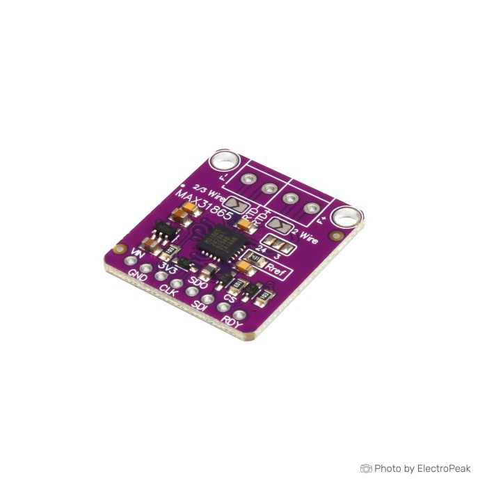
MAX31865 PT100/PT1000 RTD-to-Digital Converter Board
$3.7500
In stock
SKU
SEN-10-062
Volume discounts:
- +25 4 % $3.6000
- +100 6 % $3.5200
- +300 8 % $3.4500
- +500 10 % $3.3700
- +1000 12 % $3.3000
Ships in 2-3 business days, then:
Free delivery in 12-15 days by Tracked Economic Shipping on orders over $100.
Free delivery in 7-10 days by Express Shipping on orders over $300.
More shipping info

Shop with confidence Learn More
 WX-101W Thermostat Temperature Control Switch Module Previous
MAX31865 PT100 RTD Converter Review
The MAX31865 PT100/PT1000 RTD-to-Digital Converter Board is an SPI breakout for reading platinum resistance temperature detectors with microcontrollers such as Arduino, ESP32, or Raspberry Pi. It supports PT100 to PT1000 sensors in 2-wire, 3-wire, and 4-wire configurations. Although the onboard converter IC supports both probe classes, this board uses a 430 Ω reference resistor, making PT100 the practical out-of-box hardware configuration. Buyers planning to read a PT1000 probe, expecting a plug-and-play assembly, or needing thermocouple support should review the hardware details before purchasing.
For a broader comparison of sensing approaches, browse our temperature and humidity sensors catalog. Our guide to choosing an Arduino-compatible temperature sensor compares resistance elements, thermistors, and integrated silicon sensors.
Specifications of MAX31865 PT100/PT1000 RTD-to-Digital Converter Board
- Compatible with PT100 to PT1000 sensors
- Compatible with 2-wire RTD connections
- Compatible with 3-wire RTD connections
- Compatible with 4-wire RTD connections
- Interface: SPI
- ADC resolution: 15-bit
- Nominal temperature resolution: 0.03125 °C
- Overvoltage protection: Yes
- Fault detection: Open sensor detection
- Fault detection: Short circuit detection
- Fault detection: Out-of-range error detection
- Board dimensions: 25.5x28 mm
MAX31865 PT100 Module Specifications Explained
These specifications translate directly into practical system-design decisions during prototyping.
| Specification | Technical Value | Why It Matters |
|---|---|---|
| Host Interface | SPI (Modes 1 and 3) | Requires four signal lines (SCLK, MOSI, MISO, CS) plus power and ground. An independent chip-select line for each board lets multiple RTD modules share one hardware SPI bus on the host controller. |
| ADC Resolution | 15-bit | Provides fine digital granularity across the full platinum RTD resistance curve, but total measurement accuracy still depends on sensor class, lead resistance, and reference resistor tolerance. |
| Temperature Resolution | 0.03125 °C nominal | Indicates the smallest step size readable by the internal converter math. It is a conversion-resolution figure, not an end-to-end absolute-accuracy guarantee. |
| Fault Detection | Open sensor, short circuit, out-of-range | The MAX31865 monitors sensor-line continuity and voltage limits through an internal diagnostic register. Firmware must query this register to detect disconnected leads or probe faults during runtime. |
| Overvoltage Protection | Yes (±45 V on RTD inputs) | Datasheet-level protection applies to the dedicated analog sensor input pins, protecting the IC against accidental static or moderate line transients. It does not apply to power input pins or the SPI bus. |
| Physical Size | 25.5x28 mm | A compact footprint for project enclosures, control boxes, or 3D printer controller assemblies where space near the mainboard is restricted. |
MAX31865 PT1000 and RTD Wire Configuration
The MAX31865 converter IC is architecturally compatible with PT100 to PT1000 sensors, but the physical board configuration determines actual performance. The installed reference resistor (RREF) sets the reference point used to calculate sensor resistance. This board is populated with a 430 Ω (0.1%) reference resistor. In platinum RTD systems, a 430 Ω reference resistor is designed specifically for PT100 elements, which measure 100 Ω at 0 °C. A PT1000 element, measuring 1,000 Ω at 0 °C, typically requires a 4.3 kΩ reference resistor to balance ADC dynamic range and measurement math. Using a PT1000 sensor with a 430 Ω reference resistor requires hardware modification or custom software scaling that deviates from standard driver workflows.
The board supports 2-wire, 3-wire, and 4-wire RTD configurations. Each has its own cabling and installation trade-offs:
- 2-Wire: Connects the probe across two terminals without compensating for lead wire resistance. Wire resistance adds directly to the RTD reading, creating temperature offsets over longer cable runs.
- 3-Wire: Uses a third lead to measure and mathematically cancel lead resistance. This is the standard industrial configuration, though generic boards typically require specific solder-jumper settings or trace cuts on the PCB to route the third terminal to the MAX31865 force/sense pins.
- 4-Wire: Provides true Kelvin sensing with separate current-excitation and voltage-sensing pairs, eliminating lead wire error entirely. This arrangement requires four conductors back to the probe head.
Inspect your probe type before purchasing. This board cannot read a thermocouple; for an SPI-based K-type probe interface, use a K-type thermocouple interface such as the MAX6675 Thermocouple Module, along with our guide to K-type thermocouple Arduino setup. If you are assembling a custom probe element, fitting the sensor inside a matching RTD probe protection case helps shield the assembly from mechanical impact and fluid contact.
MAX31865 RTD Converter Limitations
These hardware boundaries matter in demanding builds:
- Resolution vs. Accuracy: The 0.03125 °C nominal resolution represents conversion granularity. Real measurement accuracy depends on your RTD tolerance class (Class B, Class A, or 1/10 DIN), RREF component tolerance, cable length, and electrical noise.
- Lead Resistance in 2-Wire Setups: In 2-wire configurations, lead wire resistance directly distorts sensor output. On long or thin cable runs, this resistance has been observed to introduce offsets of several degrees if left uncompensated.
- Conversion Timing: Starting a conversion is not instantaneous. The MAX31865 requires approximately 55 ms under 60 Hz mains filter mode, or 66 ms under 50 Hz filter mode, before a valid conversion result is ready in the data registers.
- Active Fault Handling: Fault-detection registers flag open circuits, short circuits, or voltage thresholds, but they do not resolve electrical problems automatically. Firmware routines must poll and clear fault flags after an event.
- Board Specification Boundaries: The board does not include formal isolation, industrial surge certification, or factory calibration certificates. Supply voltage and logic-level tolerance are not explicitly documented on the raw PCB, so verify board silk and components before wiring to 5 V logic.
For a direct visual readout instead of an SPI microcontroller connection, an external standalone K-type temperature display such as the XH-B310 LED Panel Thermometer offers an integrated panel-mount solution without code development.
MAX31865 RTD Converter Compatibility and Setup
The MAX31865 communicates over standard SPI in SPI Mode 1 or Mode 3. It interfaces with microcontrollers that provide SPI master peripherals, including ESP32, STM32, Arduino boards, and single-board computers running Linux or Zephyr OS with existing MAX31865 kernel drivers.
| System Area | Requirements & Configuration |
|---|---|
| Host Connections | SCLK, MOSI (SDI), MISO (SDO), CS, Power, Common Ground |
| Microcontroller Support | Arduino, ESP32, Raspberry Pi, STM32, Zephyr-supported platforms |
| Operating System Support | Native kernel tree drivers in Linux and upstream RTOS support in Zephyr |
| Firmware Settings | Requires setting R_REF (typically 430.0 for this board) and R0 (100.0 for PT100) |
| Conversion Latency | Allow ~55 ms (60 Hz filter) or ~66 ms (50 Hz filter) per one-shot reading |
| Connector Assembly | Supplied terminal blocks and pin headers require soldering prior to wiring |
Verify your first reading with this direct sequence:
- Solder the included terminal blocks and pin header to the breakout board.
- Check the marking on the onboard reference resistor, labeled near the IC and confirming 430 Ω.
- Configure the probe wiring. In 3-wire mode, bridge the designated solder pads indicated by the board silkscreen to route the sense lines.
- Connect the SPI bus lines and power to your microcontroller with reliable SPI jumper wiring, maintaining a shared common ground.
- In firmware, configure SPI Mode 1 or 3, define the reference resistor as 430.0 Ω, and set the nominal resistance to 100.0 Ω.
- Enable VBIAS, trigger a conversion, wait at least 65 ms, then read the resulting temperature and fault registers.
- Compare the room-temperature reading with a reference thermometer before deploying it into a closed loop.
MAX31865 RTD Converter Accessories
The MAX31865 breakout is a bare interface module. You need supporting hardware to complete an active measurement circuit:
Required
- Platinum RTD Probe: A PT100 temperature probe (2-wire, 3-wire, or 4-wire) matching the board's 430 Ω reference configuration. Probes are sold separately.
- SPI-Capable Host: A microcontroller or single-board computer with a free GPIO for chip-select control.
- Soldering Equipment: Solder and an iron to install the terminal blocks and header pins.
- DC Power Supply and Ground: Clean power and a shared ground reference with the host MCU.
Recommended
- Prototyping Jumper Wires: A 140-piece Breadboard Jumper Wire Kit simplifies pin-to-pin connections during initial bench testing.
- Prototyping Surface: An 830-point breadboard provides stable mounting for breakout boards, resistors, and host connections.
- Digital Multimeter: Essential for checking continuity across RTD wiring terminals and confirming reference resistor resistance.
- 3-Wire or 4-Wire Cabling: Shielded multi-conductor wiring reduces noise and eliminates lead resistance errors on runs over two meters.
Optional
- Sensor Protection Casing: A 6x50mm stainless steel case for PT100 and DS18B20 temperature sensors provides mechanical shielding when potting bare RTD elements.
- Shielded Instrument Cable: Recommended when routing RTD wiring past AC motors, relays, or switching power supplies.
- Additional MAX31865 Modules: For multi-channel RTD monitoring, use separate chip-select lines per module on the same SPI bus.
MAX31865 PT100 Module FAQ
Does this MAX31865 board work with PT1000 probes?
Not without matching hardware configuration. The MAX31865 IC supports PT1000 math, but this board is populated with a 430 Ω reference resistor tailored for PT100 sensors. A PT1000 sensor requires a 4.3 kΩ reference resistor for standard ADC scaling and proper driver-library calculation.
Is the MAX31865 PT100 module a thermocouple reader?
No. The MAX31865 is strictly a resistance-to-digital converter for platinum resistance elements. It cannot read voltage-generating junctions such as K-type, J-type, or T-type thermocouples.
Is an RTD temperature sensor included with the board?
No. The board ships with unsoldered screw terminals and a male header strip, but it does not include an RTD probe or hookup wires.
Can I use 2-wire, 3-wire, and 4-wire RTD probes?
Yes. The board supports all three wiring styles. Connecting a 3-wire or 4-wire probe typically requires bridging designated solder pads or altering surface traces according to the PCB silkscreen markings.
Can I use this MAX31865 board with Arduino, ESP32, Raspberry Pi, Linux, or Zephyr?
Yes. Any controller capable of SPI communication in Mode 1 or Mode 3 can interface with the board. Linux and Zephyr both include driver subsystems for the MAX31865 IC family.
Why is my MAX31865 temperature reading wrong or implausible?
Incorrect readings result from mismatched software constants, such as using 400 Ω or 4300 Ω in code instead of the 430 Ω resistor on the board, unconfigured wire jumpers, floating SPI pins, or failure to clear active fault register states.
Does 0.03125 °C resolution mean 0.03125 °C accuracy?
No. That value is nominal mathematical resolution from the 15-bit ADC. Real measurement accuracy depends on your sensor's IEC class, lead wire compensation, reference resistor accuracy, and electrical noise.
What should I use instead if I need a different kind of temperature sensor?
For wet environments that need digital communication without an analog interface board, consider a sealed waterproof digital temperature probe such as the DS18B20. Simple analog circuits can use an absolute Kelvin-calibrated analog sensor (LM335) or a linear Celsius analog temperature sensor (LM35DZ), both of which connect directly to analog ADC pins. For moving or electrically live surfaces, consider non-contact infrared temperature sensing with the MLX90614.
Purchase Decision Summary
Ideal for:
- Makers using standard PT100 probes who need high-resolution digital data over SPI.
- Arduino, ESP32, Raspberry Pi, or embedded Linux projects that require multi-wire RTD compensation.
- Developers comfortable soldering headers, setting hardware jumpers, and validating firmware constants.
Maybe for:
- PT1000 users with the tools and experience to swap the surface-mount reference resistor to 4.3 kΩ.
- Prototyping setups where 2-wire cable runs are short enough for lead resistance to remain negligible.
Consider another option if:
- Your system uses thermocouples, thermistors, or semiconductor sensors.
- You need a pre-assembled, tool-free temperature measurement system with an integrated probe.
- Your project requires factory-calibrated, certified industrial instrumentation out of the box.
Buying Checklist
- Confirm your sensor is a platinum RTD (PT100), not a thermocouple.
- Verify whether your installation will use 2-wire, 3-wire, or 4-wire cabling.
- Ensure you have a soldering iron and solder ready to attach the terminal blocks and header.
- Check that your host controller has SPI capability and a dedicated GPIO for chip select.
- Ensure you have an RTD probe, as no sensor probe is included with the module.
- Confirm that you can supply stable logic power and a common ground reference.
- Plan to set software driver constants to
RREF = 430.0andRNOMINAL = 100.0.
| Interface Type | SPI |
|---|---|
| Operating Voltage (V) | 3.3V, 5V |
| Operating Temp (°C) | -40 to 85 |
| Dimensions (mm) | 25.5 x 28 mm |
| Mounting Type | Screw holes |
| IP Rating | None |
| Output Type | SPI |
| Accuracy | 0.03125°C, 0.5°C |
| Resolution | 15 bit |
| Response Time | 21 ms |
| Measurement Range | 100Ω to 1kΩ |
| Environmental Parameter | Temperature |
| Probe Type | Probe Style |
| Chipset | MAX31865 |
| Relay Output | No |
| Protocols | SPI |
| Temp Accuracy | 0.03125°C, 0.5°C |
Write Your Own Review

Please complete your information below to login.
Sign In
Create New Account