
Product added to cart

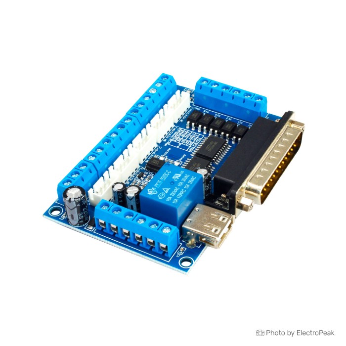
5-Axis CNC Breakout Board w Optical Coupler for Mach3
$3.2500
In stock
SKU
misc-04-040
Volume discounts:
- +25 4 % $3.1200
- +100 6 % $3.0500
- +300 8 % $2.9900
- +500 10 % $2.9200
- +1000 12 % $2.8500
Ships in 2-3 business days, then:
Free delivery in 12-15 days by Tracked Economic Shipping on orders over $100.
Free delivery in 7-10 days by Express Shipping on orders over $300.
More shipping info

Shop with confidence Learn More
 CNC 3018 Pro Engraving Machine Kit Previous
5-Axis CNC Breakout Board for Mach3 Review
This 5-axis CNC breakout board interfaces with Mach3, Linux CNC (EMC2), and CNC parallel control software, routing signals between a host computer and up to five external stepper driver channels. It combines a 12–24V input voltage range with an anti-reverse function, separated USB and peripheral power phases, opto-isolated signals, configurable machine inputs, an onboard relay output, and a 0–10V analog voltage output for inverter spindle-speed control.
It is intended for machine builders assembling a dedicated parallel-port CNC router, mill retrofit, or engraver with external stepper drives. If your machine depends on a laptop, USB-based motion control, or built-in motor power stages, you will need a different hardware architecture.
When comparing CNC control hardware, distinguish between a raw breakout board and an integrated motion controller before planning power and cabling.
Specifications of 5-Axis CNC Breakout Board w Optical Coupler for Mach3
- Compatible with MACH3: Compatible with MACH3
- Compatible with Linux CNC (EMC2): Compatible with Linux CNC (EMC2)
- Compatible software: Compatible with CNC parallel control software
- Controller design: Designed for single axis CNC single phase stepper controller
- Controller support: M542
- Controller support: MA860H
- Controller support: 2M542
- Controller support: DM860
- Stepper motor controller drivers: 5 axis maximum support
- Input voltage range: 12-24V
- Protection: Anti-reverse function
- Power arrangement: USB power supply and peripheral power phase are separated
- Signal isolation: All signals are opto-isolated
- Limit input interface: 5 input interface to define limit
- Emergency-stop input interface: 5 input interface to define emergency stop
- Cutter-alignment input interface: 5 input interface to define cutter alignment
- Relay output control interface: Relay output control interface
- Relay application: Relay output can be accessed by spindle motor
- Relay application: Relay output can be accessed by air pump
- Relay application: Relay output can be accessed by water pump
- Spindle-control output: 0-10V analog voltage output for the inverter to control the speed of the spindle
5-Axis CNC Breakout Board Specifications Explained
Knowing how the board's electrical specifications affect machine behavior helps prevent miswiring and component damage during commissioning.
| Feature | Specification | Why it matters |
|---|---|---|
| Motion Channels | 5 axis maximum support | Provides step and direction output signals for up to five external axes (typically X, Y, Z, plus dual gantry or rotary A/B axes). It contains no onboard motor drivers. |
| Driver Compatibility | M542, MA860H, 2M542, DM860 | Designed to drive industrial single-axis stepper controllers. Builders must confirm common-anode or common-cathode wiring topology against the specific driver's optocoupler inputs. |
| Power Inputs | 12–24V DC input, USB isolated phase | Separates the digital computer ground from the peripheral field wiring, protecting the host PC while providing adequate voltage to drive auxiliary switching circuits. |
| Machine Inputs | 5 configurable input interfaces | Provides five physical inputs to assign across home limits, emergency stop, and cutter alignment probes. They are shared configurable inputs rather than separate dedicated banks for each role. |
| Auxiliary Switching | Relay output control interface | Allows automated on/off control for a spindle, coolant pump, or air blast. Because contact voltage and current limits are unspecified, external contactors should be used for heavy loads. |
| Spindle Control | 0–10V analog voltage output | Generates a variable DC voltage reference to regulate spindle RPM through a variable frequency drive (VFD). Requires matching analog ground and inverter input scaling. |
| Signal Isolation | All signals are opto-isolated | Separates machine-side electrical noise from digital logic lines. This reduces false limit triggers and electrical interference, though system-wide isolation ratings are not specified. |
Need more than five CNC driver channels? The MKS Monster8 V2.0 with STM32F407 provides eight driver channels on an expanded architecture.
The board lists support for industrial drives such as the DM860 and M542, though modular options can also be used for bench testing. For external CNC motor drivers, compact modules such as the A4988 Reprap Stepper Motor Driver illustrate the separate driver requirement. Confirm pinouts and signal voltages before wiring.
Mach3 5 Axis Breakout Board Compatibility and Requirements
This interface board is built around parallel-port motion control architectures. It does not process motion calculations onboard. Instead, it passes real-time step and direction pulses directly from the host PC running compatible CNC software.
| Subsystem | Compatibility status | Requirements & notes |
|---|---|---|
| Control Software | Compatible | MACH3, Linux CNC (EMC2), and standard CNC parallel control software. |
| Host Hardware | Desktop PC with LPT port | Requires a standard DB25 parallel port. Conventional Mach3 parallel operation requires a 32-bit Windows operating system. |
| USB Connection | Power domain only | The USB connection provides 5V logic power to the board side. It does not transmit motion commands or replace the parallel cable. |
| USB-to-Parallel Adapters | Not supported | Standard USB-to-DB25 converter cables cannot maintain the deterministic, microsecond-level timing required for CNC step generation. |
| Linux CNC | Compatible | Requires a dedicated PC with acceptable real-time latency characteristics and manual HAL pin configuration. |
| Stepper Drivers | External drivers required | Accepts external step/direction drivers including M542, MA860H, 2M542, and DM860. |
| Machine Power | Dual power supplies | Requires 5V via USB for logic and 12–24V DC for peripheral inputs, relay, and 0–10V analog generation. |
The peripheral circuitry needs stable DC voltage. A dedicated supply such as the Switching Power Supply SMPS - 12V, 30A provides suitable 12–24V peripheral power, but total current capacity must account for all field sensors and auxiliary loads connected to your machine.
For desktop routers or laser engravers that need modern Wi-Fi, web, and touchscreen CNC control, the 32-bit MKS DLC32 V2 provides an alternative architecture without a legacy parallel-port computer. Compare CNC controller board options before building to ensure the host computer matches the board's communication requirements.
Mach3 Breakout Board Limitations and Setup Risks
A common setup error is treating the USB port as a motion controller connection. On this board family, USB supplies only 5V power to the PC side of the optocouplers. Motion commands must arrive through the parallel interface, so modern laptops without dedicated parallel ports cannot drive this board directly.
The board has two separate power domains. The 5V USB connection powers the digital signal inputs, while the 12–24V DC terminal powers the input optocoupler field side, relay coil, and 0–10V analog conversion circuitry. Without the 12–24V supply, stepper signals may still pass through from the parallel port, but limit switches, emergency stop inputs, spindle speed control, and the onboard relay will not operate.
The listing states that the relay output can be accessed by a spindle motor, water pump, or air pump, but it provides no relay contact voltage or current ratings. Routing mains AC voltage or heavy inductive motor loads directly through unrated PCB traces creates severe safety and fire risks. Always place a properly rated external contactor, solid-state relay, or industrial motor starter between this board and high-power shop equipment.
The 0–10V analog output provides speed regulation for variable frequency drives, but the board specification does not state output linearity, load capability, or onboard calibration trim. Before connecting hardware such as the Complete set of spindle 500 watts 48 volts air-cooled, complete thorough spindle hardware and control-interface verification to confirm that the motor speed controller matches the analog output range. Review all ratings carefully when selecting spindle-control hardware.
For small-scale 3-axis or 4-axis builds where a parallel-port computer is impractical, consider Arduino and GRBL CNC control with the Arduino CNC Shield V3, which runs directly over standard USB serial connections.
5-Axis CNC Breakout Board Accessories and System Parts
A breakout board is an interface component, not a standalone controller. A working machine needs several external sub-assemblies to complete the motion and safety loops.
Selecting compatible CNC machine components helps ensure that external logic, motor drivers, and power supplies operate reliably together.
Required System Parts
- Host PC with Parallel Port: A desktop computer equipped with an onboard or PCI/PCIe DB25 parallel port running 32-bit Windows (for Mach3) or Linux (for Linux CNC).
- DB25 Parallel Cable: A straight-through DB25 male-to-female or male-to-male cable (depending on host port gender) to route motion data. Package inclusion is not specified.
- USB Power Cable: A standard USB cable to draw 5V logic power from the host computer or a separate 5V adapter. Package inclusion is not specified.
- 12–24V DC Power Supply: A clean DC power source for the peripheral terminal block, such as the Switching Power Supply SMPS - 12V, 30A.
- External Stepper Motor Drivers: Independent single-axis drives (e.g., M542, DM860) to power each axis.
- Stepper Motors & Motor Supply: Machine motion requires pairing stepper motors and external drivers such as the NEMA 17HS8401 1.7A Stepper Motor with an appropriately sized high-voltage motor power supply.
- Machine Safety Wiring: A dedicated, normally closed Emergency Stop switch wired to one of the five input terminals.
Recommended Accessories
- Digital Multimeter: Essential for checking supply polarities, verifying 5V and 12–24V rail isolation, and measuring 0–10V output voltages before connecting sensitive hardware.
- Interposing Relays / Solid State Relays: Correctly rated switching devices placed between the board's unrated relay contacts and AC mains or inductive pump motors.
- Shielded Signal Cabling: Grounded shielded wiring for all limit switches, emergency stop buttons, and stepper step/direction lines to eliminate electrical noise interference.
- DIN Rail or Enclosure: A grounded metal electrical enclosure with proper terminal blocks and wire ducting to protect the board from dust and conductive chips.
Optional Additions
- Spindle VFD System: An inverter-driven spindle motor that accepts an external 0–10V analog speed reference.
- Homing Limit Switches & Probes: Mechanical microswitches, inductive proximity sensors, or touch probes wired to the remaining configurable input pins.
- Coolant / Air Solenoid: Low-voltage DC valves controlled via the onboard relay output to automate tool cooling.
Mach3 5 Axis Breakout Board Quick Start
Commission this breakout board methodically to isolate configuration errors before applying high voltage to motor drives.
- Inspect the Board: Examine current inventory markings to confirm terminal labels, power polarities, and port pinouts. Do not assume pin mappings without checking PCB silk screening.
- Establish Logic Power: Connect the USB cable to supply 5V logic power. Connect a verified 12–24V DC power supply to the peripheral power terminals, observing correct polarity.
- Connect Parallel Cable: Secure the DB25 cable between the host computer's parallel port and the board.
- Configure Host Software: In Mach3 or Linux CNC, configure the LPT port address (typically 0x378 for onboard ports). Assign the step and direction pins for the X-axis according to the board's terminal chart.
- Wire a Single Driver: Connect step (PUL), direction (DIR), and enable (EN) lines to a single external driver. When testing single-axis movement with modular drivers such as the A4988 Reprap Stepper Motor Driver, confirm logic voltage requirements and signal levels before applying power.
- Test Axis Jogging: Power up the external driver and execute a low-speed jog command in software. Confirm motor rotation and direction. If the motor locks but does not turn, verify active-high versus active-low step pulse settings.
- Wire Machine Inputs: Connect an Emergency Stop switch to one of the five input interfaces. In software, configure the assigned pin, test that triggering the switch halts software motion, and repeat for limit switches.
- Verify Spindle Output: Command a maximum spindle speed (M3 S24000) in software and measure the voltage across the analog output terminals with a multimeter. Confirm it scales smoothly from 0V to 10V before attaching VFD control lines.
- Wire Auxiliary Relay: Connect low-voltage control signals to the relay terminals. Test switching behavior with software M8 (coolant on) and M9 (coolant off) commands.
Common initial setup issues include missing 12–24V peripheral power, which causes dead inputs and no 0–10V output; an incorrect parallel port memory address in Mach3; inverted active-low emergency stop logic; and attempts to run motion data through the USB connection.
For applications better suited to GRBL-based entry-level CNC control, the Makerbase MKS DLC V2.1 offers a simpler firmware path running directly on an 8-bit ATmega328P platform without dedicated parallel-port hardware.
Mach3 5 Axis Breakout Board FAQ and Buying Checklist
Is this a USB CNC motion controller?
No. This is a parallel-control breakout board that uses the USB connector strictly for 5V logic power. Motion data must travel through a standard DB25 parallel interface from a PC running Mach3 or Linux CNC.
Does this board include five stepper motor drivers?
No. The board has no onboard motor power stages. It provides step and direction logic terminals for up to five external stepper motor controller drivers, including M542, MA860H, 2M542, or DM860 units.
Will this work with Mach3 and Linux CNC?
Yes. The board is compatible with MACH3, Linux CNC (EMC2), and standard CNC parallel control software. Successful operation requires a PC with a functional parallel port and proper software pin configuration.
Will it work with a laptop or USB-to-parallel adapter?
No. Standard USB-to-parallel adapter cables do not support real-time CNC step generation and will not work. Reliable operation requires an authentic hardware parallel port built into a desktop motherboard or installed through a PCI/PCIe expansion card.
Why does the board use both USB power and a 12–24V input?
The two power inputs serve electrically isolated power domains. USB supplies 5V to the computer-side logic and optocouplers, while the 12–24V supply powers the machine-side input circuits, the onboard switching relay, and the 0–10V analog spindle circuit.
Can I connect the relay directly to a spindle motor or water pump?
No. Direct connection to high-voltage or heavy inductive loads is not recommended because relay contact ratings are not specified. Wire the board's relay contacts to trigger an appropriately rated external contactor or solid-state relay.
Will the 0–10V output work with my VFD or inverter?
Yes, provided your variable frequency drive accepts a standard 0–10V DC analog speed reference signal. Confirm the inverter's terminal labeling, analog input configuration, and common ground wiring before connecting.
Are all connections safety-rated because the board is opto-isolated?
No. Although the board incorporates optical couplers to isolate logic signals from field-wiring noise, it does not carry verified industrial safety ratings or high-voltage isolation certifications. High-voltage isolation must be handled with certified external equipment.
Purchase Decision Summary
- Ideal for: CNC builders running Mach3 or Linux CNC on a dedicated desktop PC with an authentic parallel port who need to control up to five external stepper drivers, assign machine limits, switch an auxiliary device, and control spindle RPM via a VFD.
- Maybe for: Experienced makers retrofitting older CNC machines who are comfortable measuring terminal voltages, configuring software pin tables manually, and installing external contactors for high-power switching.
- Avoid if: You only have a laptop, require plug-and-play USB motion control, need onboard stepper drivers, intend to switch mains AC loads directly on the PCB, or need wireless/touchscreen operation.
Buying Checklist
- [ ] My host computer has an authentic DB25 parallel port running a compatible OS (such as 32-bit Windows for Mach3, or Linux CNC).
- [ ] I understand that the USB connection provides 5V power only and does not carry motion control data.
- [ ] I have budgeted for separate external stepper motor drivers, stepper motors, and a high-voltage motor power supply.
- [ ] I have a dedicated 12–24V DC power supply available to power the peripheral inputs, relay, and 0–10V analog circuits.
- [ ] I have straight-through DB25 and USB cables available for installation.
- [ ] I will use external, rated contactors or relays rather than switching mains spindle or pump loads directly on the board.
- [ ] My spindle inverter accepts a standard 0–10V analog input reference for speed control.
- [ ] I have planned my five machine inputs across my required limits, home switches, E-stop, and touch probe.
If your build environment cannot support a dedicated parallel-port PC, review other CNC control approaches before committing to this architecture.
| Platform | MACH3, Linux CNC (EMC2) |
|---|---|
| Interface Type | Parallel,USB |
| Operating Voltage (V) | 12-24V |
| Dimensions (mm) | 100mm x 80mm x 25mm |
| Mounting Type | Screw holes |
| Control Type | Relay (Electromechanical) |
| Channel Count | 5 |
| Control Signal | Analog, PWM |
| Relay Type | Relay output |
| Display Type | None |
| Material | FR4 |
| Input Type (AC/DC) | DC |
| Protocols | MACH3,Linux CNC (EMC2) |
Write Your Own Review

Please complete your information below to login.
Sign In
Create New Account