
Overview
What You Will Learn
- What compass module is?
- Compass module and Arduino interface.
- Make a digital compass with the GY-511 module and Arduino.
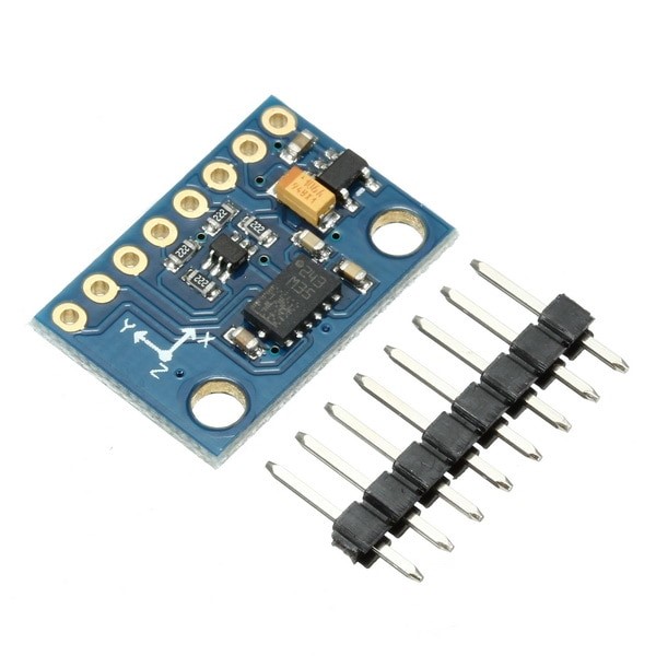
General Information about Compass Module
Tip
Required Materials

Hardware Components
Software Apps
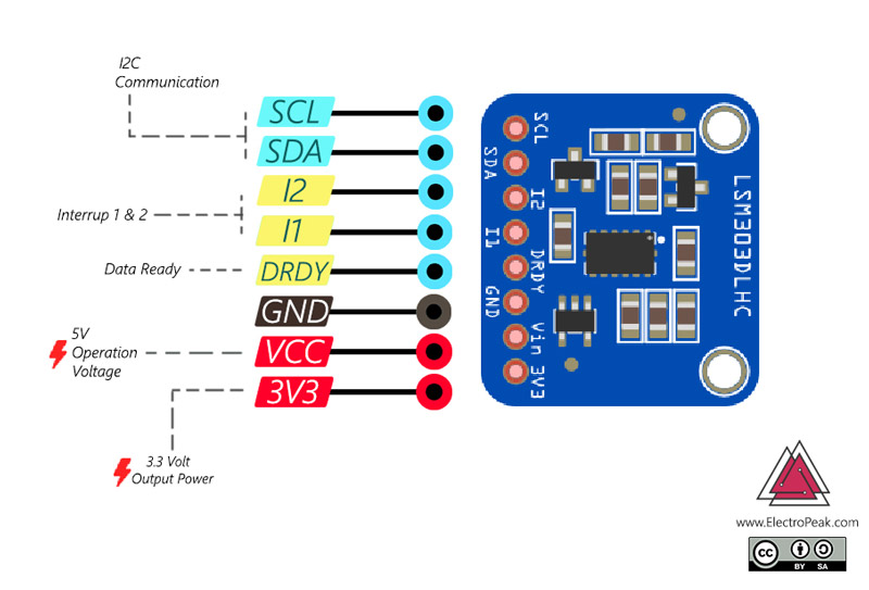
Interfacing GY-511 Compass Module with Arduino
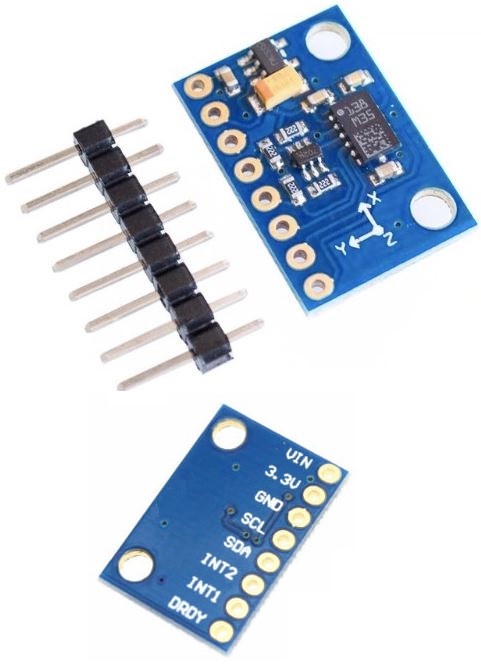
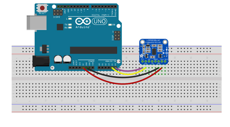
GY-511 compass module has 8 pins, but you need only 4 of them to interface with Arduino. This module communicates with Arduino using I2C protocol, so connect the SDA (I2C output) and SCK (I2C clock input) pins of the module to the I2C pins on the Arduino board.
Note
GY-511 Compass Module Calibration
In order to navigate, you first need to calibrate the module, which means to set the measuring range from 0 to 360 degrees. To do this, connect the module to Arduino as shown below and upload the following code on your board. After executing the code, you can see the minimum and maximum values of the measuring range for X, Y and Z axis in the serial monitor window. You will need these numbers in the next part, so write them down.
Circuit
Code
In this code, you need the Wire.h library for I2C communication, and LMS303.h library for the compass module. You can download these libraries from the following links.
Note
/*
Compass Calibration
by Hanie Kiani
Home
*/
#include <Wire.h>
#include <LSM303.h>

LSM303 compass;
LSM303::vector<int16_t> running_min = {32767, 32767, 32767}, running_max = {-32768, -32768, -32768};

char report[80];

void setup() {
  Serial.begin(9600);
  Wire.begin();
  compass.init();
  compass.enableDefault();
}

void loop() {
  compass.read();

  running_min.x = min(running_min.x, compass.m.x);
  running_min.y = min(running_min.y, compass.m.y);
  running_min.z = min(running_min.z, compass.m.z);

  running_max.x = max(running_max.x, compass.m.x);
  running_max.y = max(running_max.y, compass.m.y);
  running_max.z = max(running_max.z, compass.m.z);

  snprintf(report, sizeof(report), "min: {%+6d, %+6d, %+6d}    max: {%+6d, %+6d, %+6d}",
    running_min.x, running_min.y, running_min.z,
    running_max.x, running_max.y, running_max.z);
  Serial.println(report);

  delay(100);
}
Let’s see some of the new functions:
compass.enableDefault();Module initialization
compass.read();Reading the output values of compass module
   running_min.z = min(running_min.z, compass.m.z);
  running_max.x = max(running_max.x, compass.m.x);
Determining the minimum and maximum values of measurement range by comparing the measured values.
Making a Digital Compass
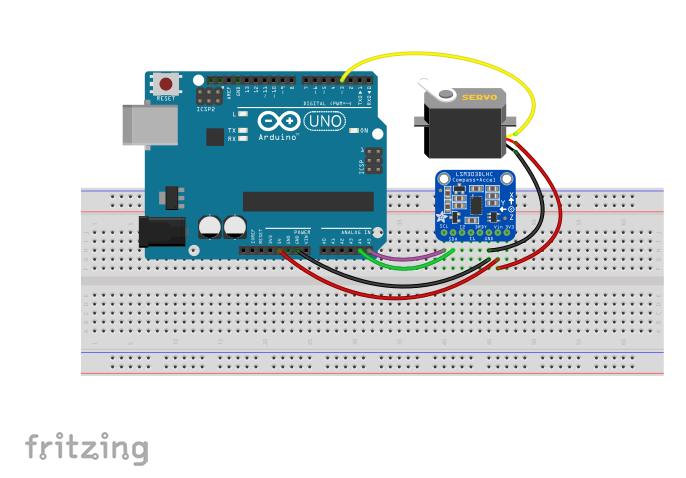
After calibrating the module, we are going to build a compass by connecting a servo motor to the module. So that the servo indicator, always shows us the north direction, like the red arrow on the compass. To do this, first the compass module calculates the geographic direction first and send it to Arduino and Then, by applying an appropriate coefficient, you’ll calculate the angle that the servo motor should rotate so that its indicator points to the magnetic north. Eventually, we apply that angle to the servo motor.
Circuit
Code
For this part you also need the Servo.h library, that is installed on your Arduino software by default.
/*
Compass Calibration
by Hanie Kiani
Home
*/
#include <Wire.h>
#include <LSM303.h>
#include <Servo.h>
LSM303 compass;
int servoPin = 3;
Servo Servo1;
void setup() {
  Serial.begin(9600);
  Wire.begin();
  Servo1.attach(servoPin);
  compass.init();
  compass.enableDefault();


  compass.m_min = (LSM303::vector<int16_t>){-32767, -32767, -32767};
  compass.m_max = (LSM303::vector<int16_t>){+32767, +32767, +32767};
}

void loop() {
  compass.read();


  float heading =compass.heading((LSM303::vector<int>){0, 0, 1});

  Serial.println(heading);
  Servo1.write(180-heading);
  delay(100);
}
Let’s see some of the new functions:
Servo Servo1;Module initialization
compass.read();Introducing the servo motor object
  Servo1.attach(servoPin);
 compass.init();
compass.enableDefault();Servo1.attach() argument is the number of the pin connected to the servo motor. compass.m_min = (LSM303::vector){-32767, -32767, -32767};
compass.m_max = (LSM303::vector){+32767, +32767, +32767};Using these lines you define the minimum and maximum values for measuring the range obtained in the previous part.
float heading =compass.heading((LSM303::vector){0, 0, 1}); float heading =compass.heading((LSM303::vector){0, 0, 1});The heading() function returns the angle between the coordinate axis and a fixed axis. You can define the fixed axis with a vector in the function argument. For example, here, by defining the (LSM303 :: vector ) {0, 0, 1}, the Z axis is considered as a constant axis.
Servo1.write(heading);Servo1.write() function applies the read value by the compass module to the servo motor. 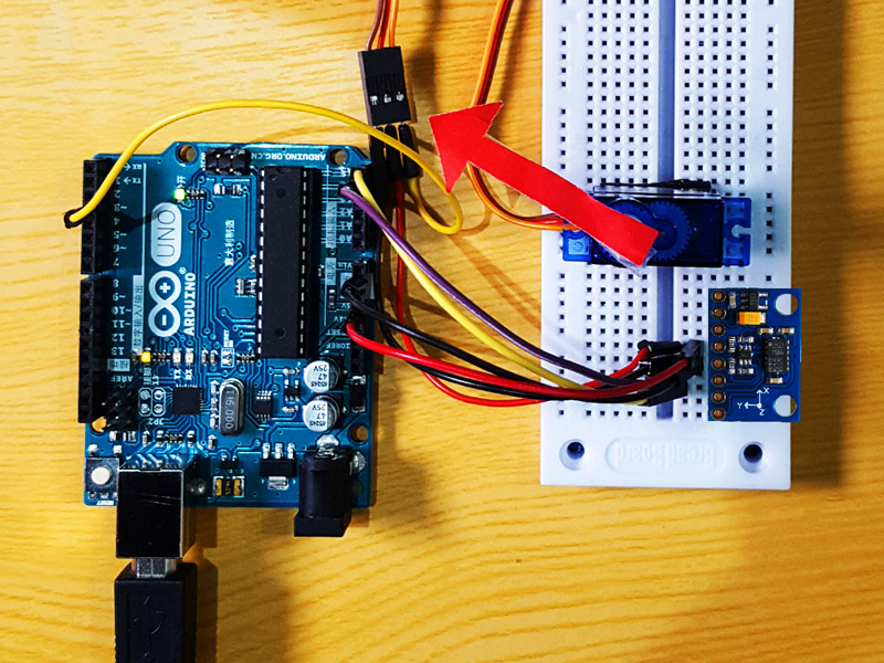
Note
What’s Next?
- Add the ESP8266 module to the system to report your position to your mobile phone at any moment.

Comments (2)
Unable to calibrate. I get this error:
‘compass’ does not name a type
Hi,
I just compiled the code and there were no errors. So, the code seems fine. Your error might be related to the libraries that the code needs. Make sure you have LSM303 library installed on your Arduino IDE.