
Mojo V3 FPGA Development Board Features
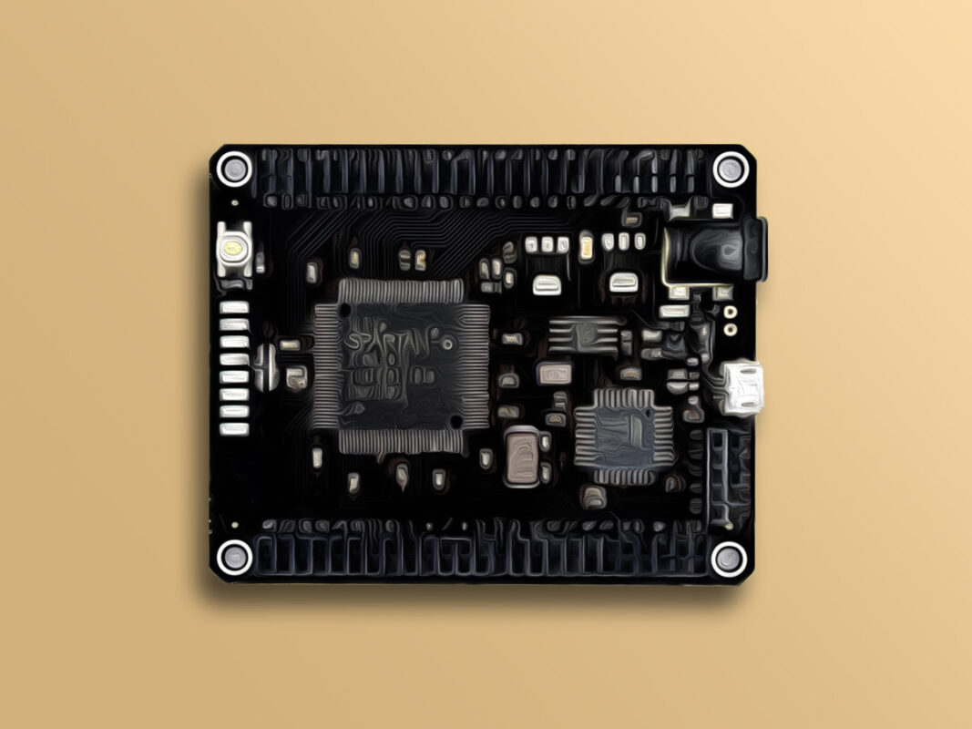
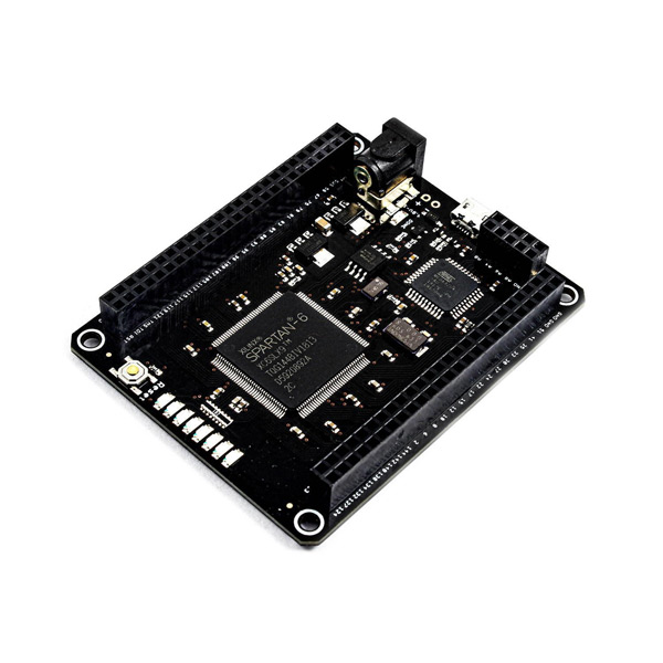
Mojo V3 is an FPGA development board of the Spartan 6 series, which lets you get the pleasure of configuring digital circuits on Mojo v3 based on your own specifications. What separates this FPGA from the others is the ease of use. The goal of Mojo v3 is to get you up and running with FPGA as easily as possible.
The Mojo V3 FPGA Board uses the Spartan 6 and a high performance ATmega32U4 microcontroller. This board has high processing power. The ATmega32U4 microcontroller comes with a USB (DFU) bootloader, which allows you to install new versions of the firmware without the need for a programmer. Once the board is powered on, the ATmega32U4 configures the FPGA from the flash memory. After the FPGA is successfully configured, your FPGA will start talking to the microcontroller; giving you access to the serial port and analog inputs.
To download the datasheet of Spartan 6 Board, click here.
To download the datasheet of ATMega32U4 Microcontroller, click here.
To download the Schematics, click here.
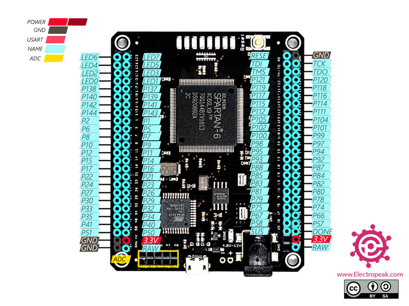
Mojo V3 FPGA Development Board Pinout
The FPGA Mojo3 board has 110 pins:
- 3V: Module power supply
- GND: Ground
- RAW: Regulator input power supply – 3.3V
- P1 ~ P144: Digital input and output pins
- A0 ~ A9: Analog pins
- AREF: Analog Reference voltage
- RES: Reset – setting as switch
- DONE: Backlight control
- SUSPEND: If this option is selected, the GSR pin will be pulsed when the FPGA wakes up from suspend mode. For more information, click here.
- TDO: Serial output for all JTAG instruction and data registers
- TMS: This pin determines the sequence of states through the TAP controller on the rising edge of TCK
- TCK: JTAG Test Clock
- TDI: Serial input to all JTAG instruction and data registers
- DONE: Backlight control
- LED1 ~ LED7: LED display
For more information, visit here.
You can see the pinout of this board in the image below.
Required Materials
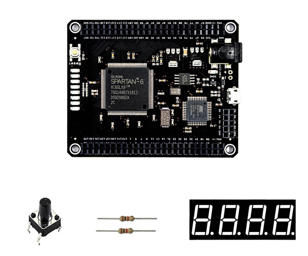
Hardware Components
How to Make a Counter with Mojo V3 FPGA Development Board
Step 1: Circuit
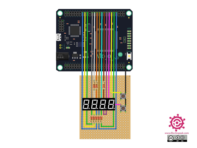
The following circuit shows how you should connect the components to the Mojo3 Board. Connect wires accordingly.
Note:
We recommend soldering the 7-segment with the resistors on a solderable prototype PCB breadboard and connecting it to the Mojo3 board using header pins or jumper wires.
Tip
If you need more help with installing the Mojo IDE, read this tutorial: A Complete Beginner’s Guide to Mojo V3 FPGA Board
Step 2: Code
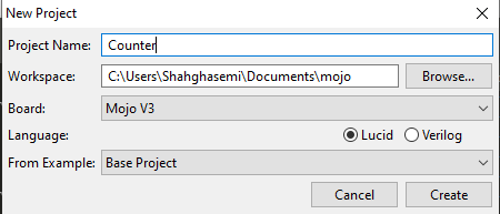
First, we need to define the pins we are going to use. For that, open Mojo IDE. In the “File” menu, click on “New Project” and fill in the blanks according to the following image.
Click on “Constraints” from the menu on the left and click on “New Constraints” section.
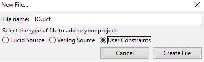
Now fill in the “File Name” with any name you want, choose the “User Constraints” option and click on “Create File”.
Now open the file you’ve created from the “Constraints” menu and enter the code below.
NET "seg<7>" LOC = P12  | IOSTANDARD = LVTTL;//A
NET "seg<6>" LOC = P2   | IOSTANDARD = LVTTL;//B
NET "seg<5>" LOC = P134 | IOSTANDARD = LVTTL;//C
NET "seg<4>" LOC = P24  | IOSTANDARD = LVTTL;//D
NET "seg<3>" LOC = P22  | IOSTANDARD = LVTTL;//E
NET "seg<2>" LOC = P10  | IOSTANDARD = LVTTL;//F
NET "seg<1>" LOC = P138 | IOSTANDARD = LVTTL;//G
NET "seg<0>" LOC = P27  | IOSTANDARD = LVTTL;//DP

NET "sel<0>" LOC = P144 | IOSTANDARD = LVTTL;//segment1
NET "sel<1>" LOC = P6   | IOSTANDARD = LVTTL;//segment2
NET "sel<2>" LOC = P8   | IOSTANDARD = LVTTL;//segment3
NET "sel<3>" LOC = P15  | IOSTANDARD = LVTTL;//segment4

NET "button<0>" LOC = P140  | IOSTANDARD = LVTTL|PULLUP;//io_button 1
NET "button<1>" LOC = P142  | IOSTANDARD = LVTTL|PULLUP;//io_button 2
Note
You can change the pin numbers here if you wish to use other pins.
Right-click on the “Source” menu and choose “New Source”.
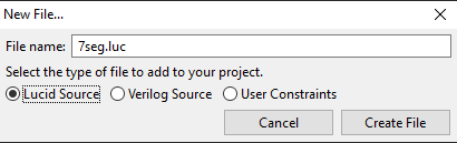
In the page opened, fill in the “File Name” with “7seg”, choose the “Lucid Source” option and create the file.
Now open the file you’ve created from the “Source” menu and enter the code below.
module segment (
    input clk,  // clock
    input rst,  // reset
    input button[2],

     output segment1,
    output segment2,
    output segment3,
    output data1,
    output data2,
    output data3,
    output data4,
    output data5,
    output data6,
    output data7,
    output data8,
    output data9,
    output data10,
    output data11,
    output data12,
    output data13,
    output data14,
    output data15,
    output data16

  )
  {

  dff counter2[20](.clk(clk));

  dff counter1[33](.clk(counter2.q[19]));


  always {
    //blinker = counter1.q[24];?
    if(button[1]==0&&button[0]==1){

      counter1.d = counter1.q+1;
    }


    else if(button[0]==0&&button[1]==1){

      counter1.d = counter1.q-1;
    }

    data1 = counter1.q[0];
    data2 = counter1.q[1];
    data3 = counter1.q[2];
    data4 = counter1.q[3];
    data5 = counter1.q[4];
    data6 = counter1.q[5];
    data7 = counter1.q[6];
    data8 = counter1.q[7];
    data9 = counter1.q[8];
    data10 = counter1.q[9];
    data11 = counter1.q[10];
    data12 = counter1.q[11];
    data13 = counter1.q[12];
    data14 = counter1.q[13];
    data15 = counter1.q[15];
    data16 = counter1.q[16];


    counter2.d = counter2.q+1;
    segment1 = counter2.q[16];
    segment2 = counter2.q[17];
    segment3 = counter2.q[18];

  }

}
In Logic Circuits, cascaded D-FlipFlops are used for designing counters. The same method is used in FPGA most of the time, too. You can a D-FlipFlop in the image below.

dff name[Number of D-FlipFlop](.clk(Connect clk first D-DlipFlop),.rst(Connect rst All D-FlipFlop));
You can make a D-FlipFlop using the “dff” command. Then you should choose a name for it. Next, the number of the D-FlipFlops cascaded to each other is chosen. Then you need to determine where the clock of the first D-FlipFlop is connected to. And finally, you can define the “rst” pins of all D-FlipFlops –This is optional-.
counter1.d = counter1.q+1;
You can use the command above to add a single D-FlipFlop to the previous cascaded D-FlipFlops.

Now open the “mojo_top.luc” file from the “Source” menu and enter the code below.
module mojo_top (

    //output led [8],         // 8 user controllable LEDs

    output seg [8],
    output sel [4],
    input button[2],


    input clk,              // 100MHz clock
    input rst_n            // reset button (active low)
  ) {

  sig rst;                 // reset signal
  sig my_array[16][8];
  sig value[4][4];

  .clk(clk) {
    // The reset conditioner is used to synchronize the reset signal to the FPGA
    // clock. This ensures the entire FPGA comes out of reset at the same time.
    reset_conditioner reset_cond;

    .rst(rst){
      segment myseg;
    }

  }

  always {
    myseg.button[0]=button[0];
    myseg.button[1]=button[1];


    reset_cond.in = ~rst_n; // input raw inverted reset signal
    rst = reset_cond.out;   // conditioned reset
    //value = 1234;

    value[0][0]=myseg.data1;
    value[0][1]=myseg.data2;
    value[0][2]=myseg.data3;
    value[0][3]=myseg.data4;

    value[1][0]=myseg.data5;
    value[1][1]=myseg.data6;
    value[1][2]=myseg.data7;
    value[1][3]=myseg.data8;

    value[2][0]=myseg.data9;
    value[2][1]=myseg.data10;
    value[2][2]=myseg.data11;
    value[2][3]=myseg.data11;


    value[3][0]=myseg.data12;
    value[3][1]=myseg.data13;
    value[3][2]=myseg.data14;
    value[3][3]=myseg.data15;

    //A,B,C,D,E,F,G,DP
    my_array[0]  = c{1,1,1,1,1,1,0,0};
    my_array[1]  = c{0,1,1,0,0,0,0,0};
    my_array[2]  = c{1,1,0,1,1,0,1,0};
    my_array[3]  = c{1,1,1,1,0,0,1,0};
    my_array[4]  = c{0,1,1,0,0,1,1,0};
    my_array[5]  = c{1,0,1,1,0,1,1,0};
    my_array[6]  = c{0,0,1,1,1,1,1,0};
    my_array[7]  = c{1,1,1,0,0,0,0,0};
    my_array[8]  = c{1,1,1,1,1,1,1,0};
    my_array[9]  = c{1,1,1,0,0,1,1,0};
    my_array[10] = c{1,1,1,0,1,1,1,0};
    my_array[11] = c{0,0,1,1,1,1,1,0};
    my_array[12] = c{0,0,0,1,1,0,1,0};
    my_array[13] = c{0,1,1,1,1,0,1,0};
    my_array[14] = c{1,0,0,1,1,1,1,0};
    my_array[15] = c{1,0,0,0,1,1,1,0};


    sel = ~c{0,0,0,0};
    //led=  c{0,0,0,0,0,0,0,0};
    seg=  my_array[15] ;


    if (myseg.segment1 == 1&&myseg.segment2 != 1&&myseg.segment3 != 1){

      //  led=  c{0,0,0,0,0,0,0,1};
      sel = ~c{0,0,0,1};
      //myseg.value = 1;
      seg=  my_array[value[0]];            //A,B,C,D,E,F,G,DP

    }
    else if (myseg.segment1 != 1&&myseg.segment2 == 1&&myseg.segment3 != 1){
      //led=  c{0,0,0,0,0,0,1,0};
      sel = ~c{0,0,1,0};
      seg=  my_array[value[1]];
    }
    else if (myseg.segment1 == 1&&myseg.segment2 == 1&&myseg.segment3 != 1){
      //led=  c{0,0,0,0,0,1,0,0};

      sel = ~c{0,1,0,0};
      seg=  my_array[value[2]];
    }
    else if (myseg.segment1 != 1&&myseg.segment2 != 1&&myseg.segment3 == 1){
      rst=1;
      //led=  c{0,0,0,0,1,0,0,0};
      sel = ~c{1,0,0,0};
      seg=  my_array[value[3]];
    }
  }
}
Now let’s take a closer look at the code above.
sig my_array[16][8];
  sig value[4][4];
Defining a 2D array to show the numbers and select the display.
segment myseg;
Connecting the main program to the counter section.
myseg.button[0]=button[0];
    myseg.button[1]=button[1];
Transfer the counter values of the buttons to the counter section.
//A,B,C,D,E,F,G,DP
    my_array[0]  = c{1,1,1,1,1,1,0,0};
    my_array[1]  = c{0,1,1,0,0,0,0,0};
    my_array[2]  = c{1,1,0,1,1,0,1,0};
    my_array[3]  = c{1,1,1,1,0,0,1,0};
    my_array[4]  = c{0,1,1,0,0,1,1,0};
    my_array[5]  = c{1,0,1,1,0,1,1,0};
    my_array[6]  = c{0,0,1,1,1,1,1,0};
    my_array[7]  = c{1,1,1,0,0,0,0,0};
    my_array[8]  = c{1,1,1,1,1,1,1,0};
    my_array[9]  = c{1,1,1,0,0,1,1,0};
    my_array[10] = c{1,1,1,0,1,1,1,0};
    my_array[11] = c{0,0,1,1,1,1,1,0};
    my_array[12] = c{0,0,0,1,1,0,1,0};
    my_array[13] = c{0,1,1,1,1,0,1,0};
    my_array[14] = c{1,0,0,1,1,1,1,0};
    my_array[15] = c{1,0,0,0,1,1,1,0};
Defining all cases to display numbers.
Now build the project and upload it to your Mojo3 Board.
In this code, you can increase or decrease the numbers displayed using two buttons.
