Contents

A complete Beginner’s Guide to Mojo V3 FPGA Board

Mojo V3 FPGA Development Board Features

Mojo is an FPGA board which lets you get the pleasure of configuring the digital circuits on Mojo v3 to your own specifications. What separates this FPGA from the others is the ease of use. The goal of Mojo v3 is to get you up and running with FPGA as easily as possible.

The Mojo v3 FPGA Board uses the Spartan 6 and a high performance ATmega32U4 microcontroller. This board has high processing power. The ATmega32U4 microcontroller comes with a USB (DFU) bootloader which allows you to install new versions of the firmware without the need for a programmer. Once the board is powered on, the ATmega32U4 configures the FPGA from the flash memory. After the FPGA is successfully configured, your FPGA will start talking to the microcontroller; giving you access to the serial port and the analog inputs.

Download the datasheet of FPGA SPARTAN 6 here.

Download the datasheet of ATMega32U4 here.

Download the Schematic of the board here.

Mojo V3 FPGA Development Board Pinout

The FPGA Mojo3 module has 110 pins:

  • 3V: Module power supply
  • GND: Ground
  • RAW: Regulator input power supply – 3.3V
  • P1 ~ P144: Digital input and output pins
  • A0 ~ A9: Analog pins
  • AREF: Analog Reference voltage
  • RES: Reset – setting as switch
  • DONE: Backlight control
  • SUSPEND: If this option is selected, the GSR pin will be pulsed when the FPGA wakes up from suspend mode. For more information, click here.
  • TDO: Serial output for all JTAG instruction and data registers
  • TMS: This pin determines the sequence of states through the TAP controller on the rising edge of TCK
  • TCK: JTAG Test Clock
  • TDI: Serial input to all JTAG instruction and data registers
  • DONE: Backlight control
  • LED1 ~ LED7: LED display

For more information visit here.

Required Materials

Hardware Components

Mojo V3 SPARTAN6 FPGA Development Board × 1

Software Apps

Mojo IDE
Xilinx ISE Design Suite

Required Software to Interface Mojo V3 FPGA Development Board

Step 1: Software Download

First, go to the link below and download Mojo IDE software and install it.

Mojo IDE software

Then download and install Xilinx ISE Design Suite software here.

Step 2: Software Setting

After finishing the installations above, open the Mojo IDE software.

Select ISE Location from Settings.

Then give the software where the Xilinx ISE Design Suite is installed.

Note

The software installation location is similar to Xilinx \ 14.7.

You must select file 14.7 or higher versions.

Success

Your software is ready to use.

Step 3: Code

Click on New Project from the File menu of Mojo IDE, and fill in the blanks as following.

Now enter the Source, and open mojo_top.luc file.

Change the generated code to following code.

/*
  Modify on March 17, 2021
  Modify by MohammedDamirchi base of Example
  
Home
*/ module mojo_top ( input clk, // 50MHz clock input rst_n, // reset button (active low) output led [8], // 8 user controllable LEDs input cclk, // configuration clock, AVR ready when high output spi_miso, // AVR SPI MISO input spi_ss, // AVR SPI Slave Select input spi_mosi, // AVR SPI MOSI input spi_sck, // AVR SPI Clock output spi_channel [4], // AVR general purpose pins (used by default to select ADC channel) input avr_tx, // AVR TX (FPGA RX) output avr_rx, // AVR RX (FPGA TX) input avr_rx_busy // AVR RX buffer full ) { sig rst; // reset signal .clk(clk) { // The reset conditioner is used to synchronize the reset signal to the FPGA // clock. This ensures the entire FPGA comes out of reset at the same time. reset_conditioner reset_cond; } always { reset_cond.in = ~rst_n; // input raw inverted reset signal rst = reset_cond.out; // conditioned reset led= c{7b0,rst}; // turn LEDs off spi_miso = bz; // not using SPI spi_channel = bzzzz; // not using flags avr_rx = bz; // not using serial port } }

Now click on Build Project and wait until the project is built.

Now click on Program Mojo (Temporary) to program your board.

This sample code is temporarily on the FPGA and the board will return to the original program by resetting.

To program the board permanently, click on Program Mojo (Flash) so that your program will run it even after if the board is reset.

This program is a sample code for testing the FPGA Mojo 3 development board, which by pressing the reset button, the embedded LED on the board turns on, and by releasing the reset button, the LED turns off again.

Liked What You See?​
Get Updates And Learn From The Best​

Comments (9)

  • Djomo Alain Reply

    Hi,
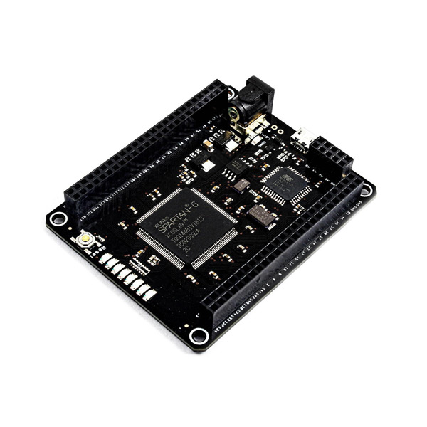
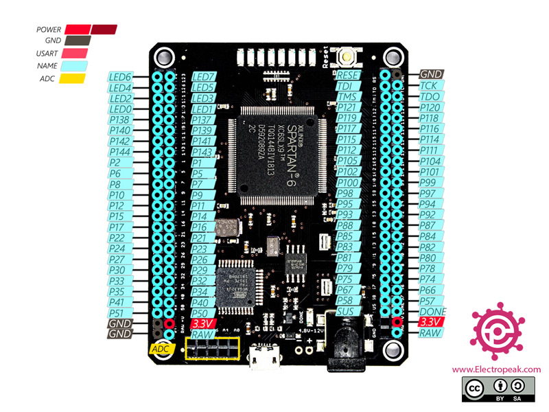
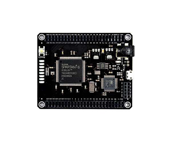
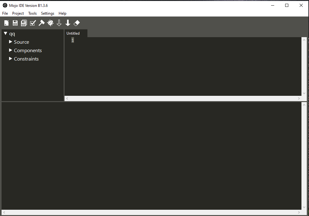
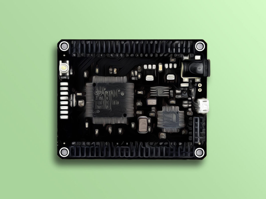
    Recently, I bought a Xilinx SPARTAN-6 board (XC6SLX9, TQG144BIV1937, D5984657A, 2C) on which is integrated an ATMEL MEGA 32U4 that I would like to use to realize my small embedded applications. But I encounter a problem when I want to download its Mojo IDE interface online, I am rather directed to Alchitry Labs, the latter once installed on my PC does not allow me to build my project.
    I want to solve this problem by installing the software required for the Mojo V3 FPGA development board interface. Please can you send me the complete Mojo IDE software with tutorials for its configuration on laptop. And I would also like to have your advice on how to install the Xilinx ISE Design Suite software associated with it.

    Thanks a lot!

    January 11, 2022 at 4:28 am
  • Djomo Alain Reply

    By the way, I really enjoyed your tutorial on the Complete Beginner’s Guide to the Mojo V3 FPGA Board!

    January 11, 2022 at 4:36 am
    • Mehran Maleki Reply

      Hi.
      You’re most welcome.
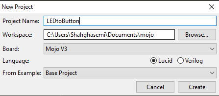
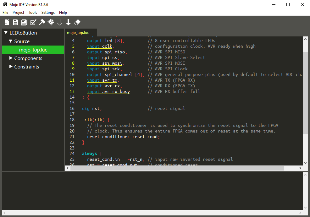
      Well, it seems that the download link for the Mojo IDE software had been corrupt. The article is now updated with a new download link. Check the new one.

      January 11, 2022 at 12:34 pm
  • Djomo Alain Reply

    thanks!

    January 13, 2022 at 12:00 am
    • Mehran Maleki Reply

      🙏

      January 15, 2022 at 6:04 am
  • Enjay Reply

    I am using the Xilinx ISE Design Suite to program the Spartan-6 on Digilent’s ANVYL development board. It took time to find a version that works on my Windows 8.1 computer but I settled for version 14.1. The latest version is 14.7. It was fairly easy to obtain a license and everything was free. i am also thinking of getting a Mojo 3 development board. With respect to the Mojo 3, can someone tell me why you need to install both the Xilinx ISE as well as the Mojo IDE — don’t they do different things? It seems to me that programming could get very complicated if you are using two different IDEs simultaneously?

    March 27, 2022 at 2:02 pm
    • Mehran Maleki Reply

      Hi,
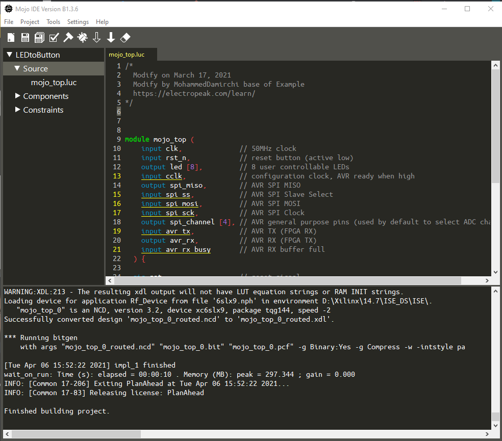
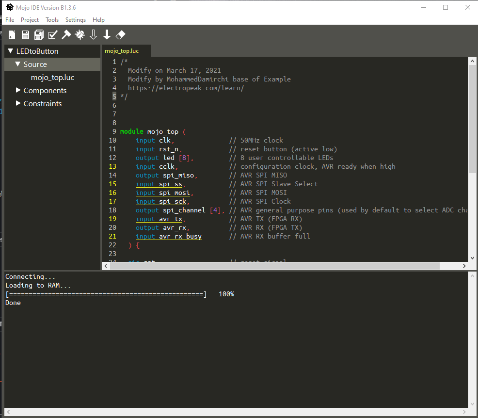
      You will not use two different IDEs simultaneously! You only need to work with the Mojo IDE to program the board. In fact, the Mojo IDE itself will be using the Xilinx ISE Design Suite software to build your projects. So, there would be nothing complicated.

      April 4, 2022 at 5:14 am
  • Krish Reply

    Could you also point me to the right place where I can find the drivers for the Mojo board ? the IDE seems to throw up “no serial port” error.

    January 6, 2023 at 3:24 pm
    • Ali Abdolmaleki Reply

      Hi dear
      did you check device managment in your PC?
      firtsaval you should see the COMPort on device managemnet when connect the board to PC.
      if you did not see , check your USB cable or change it

      March 1, 2023 at 11:20 am

Leave a Reply

Your email address will not be published. Required fields are marked *