Contents

Interfacing VNH2SP30 Monster Motor Shield with Arduino

VNH2SP30 Monster Motor Shield Features

Today, speed and direction control of DC motors is very common. These motors are widely used in manufacturing many tools and equipment. A full-bridge circuit is one of the simplest methods to control a DC motor. This method not only allows to control the motor direction, but can also be used for speed control. This shield contains a pair of VNH2SP30 full-bridge motor drivers. This driver has a higher current tolerance in compare to its similar drivers. This shield can withstand up to14A continuous current. Its power supply should be between 5.5 and 16 volts.

One of the control pins of this module is PWM. This pin is connected to the MOSFET or transistor control pin (the gate or the base), and the longer the duty cycle, the more voltage will be across the motor, resulting in faster rotation.

Note

It is necessary to use a heatsink for cooling if more than 6A is flowing through your circuit.

You can download the datasheet of this module here.

VNH2SP30 Monster Motor Shield Pinout

This Module has 17 pins:

  • VM: Module voltage
  • VCC: Module power supply
  • GND: Ground
  • A1: Positive end for motor A
  • A2: Negative end for motor A
  • B1: Positive end for motor B
  • B2: Negative end for motor B
  • PWMA: Speed control signal for motor A
  • PWMB: Speed control signal for motor B
  • AIN1: Control signal for motor A
  • AIN2: Control signal for motor A
  • BIN1: Control signal for motor B
  • BIN2: Control signal for motor B
  • EN1: Activation signal for motor A
  • EN2: Activation signal for motor B
  • C1: current measurement signal for motor A
  • C2: current measurement signal for motor B

You can see the pinout of this module in the image below.

Note that with different modes of control signals, motor performance varies. The table below shows the different modes.

Required Materials

Hardware Components

Arduino UNO R3 × 1
VNH2SP30 Monster Motor Shield × 1
Micro DC Motor 6V × 2
10 K Potentiometer × 1
9V Battery × 1
9V Battery Clips with Bare Leads × 1
Male to Male jumper wire × 1
400 Tie point Solderless Mini Breadboard × 1

Software Apps

Arduino IDE

Interfacing VNH2SP30 Monster Motor Shield with Arduino

Step 1: Circuit

After you solder the shield header pins on it, you can put it directly on the Arduino without wiring. Connect other parts to the shield accordingly.

Step 2: Code

Upload the following code to your Arduino.

 /*
  VNH2SP30-Monster-Shield
  made on 01 Nov 2020
  by Amir Mohammad Shojaee @ Electropeak
  
Home
*/ int pot; int out; #define PWM1 5 #define AIN1 7 #define AIN2 8 #define PWM2 6 #define BIN1 4 #define BIN2 9 #define EN1 A0 #define EN2 A1 void setup(){ pinMode(BIN1,OUTPUT); pinMode(AIN1,OUTPUT); pinMode(AIN2,OUTPUT); pinMode(BIN2,OUTPUT); pinMode(PWM1,OUTPUT); pinMode(PWM2,OUTPUT); pinMode(A0,OUTPUT); pinMode(A1,OUTPUT); pinMode(A5,INPUT); } void loop(){ digitalWrite(A0,HIGH); digitalWrite(A1,HIGH); digitalWrite(BIN1,HIGH); digitalWrite(BIN2,LOW); digitalWrite(AIN1,HIGH); digitalWrite(AIN2,LOW); pot=analogRead(A5); out=map(pot,0,1023,0,255); analogWrite(PWM1,out); //Speed control of Motor A analogWrite(PWM2,out); //Speed control of Motor B }

This code is for controlling two DC motors simultaneously. Turn the potentiometer clockwise to increases the motors speed.

Warning

Be careful not to turn the potentiometer completely because your motor is a 6 volts DC motor and the input voltage is 9 volts. So the motor may be damaged. Of course, you can use a lower voltage power supply or a higher voltage motor.

Liked What You See?​
Get Updates And Learn From The Best​

Comments (6)

  • seyed muhamad Reply

    hi amir,thank you for your very useful post.
    but i have a question, how i can join a hc-05 shield with this driver,if its possible, can you make me a wiring diagram for that,i mean wiring diagram for coupling UNO(or mini pro) with monster mono with hc-05.

    سلام و عرض ادب خدمت آقای شجاعی عزیز. با تشکر از مطلب بسیار مفیدی که قرار دادید. آقای شجاعی عزیز آیا امکان داره به این سیستمی که شما شماتیکش رو گذاشتید یه ماژول بلوتوث مثلا hc-05
    اضافه کرد.اگر میشه چطوری.
    با تشکر از شما

    April 12, 2021 at 6:32 pm
    • Mehran Maleki Reply

      Hi.
      Since the VNH2SP30 motor driver shield doesn’t occupy all Arduino board pins, you can add some other modules to the project too. The following links show you how you can connect the hc-05 Bluetooth module to the Arduino board with the code you need. “https://electropeak.com/learn/tutorial-getting-started-with-hc05-bluetooth-module-arduino/”,”https://electropeak.com/learn/interfacing-hc-05-bluetooth-wireless-module-with-arduino/”
      All you need to do is to connect both the VHN2P30 motor driver shield and the hc-05 Bluetooth module to the Arduino board and merge both their codes into one .ino file, and it will be fine.

      April 13, 2021 at 4:52 am
  • سیدمحمدحسن Reply

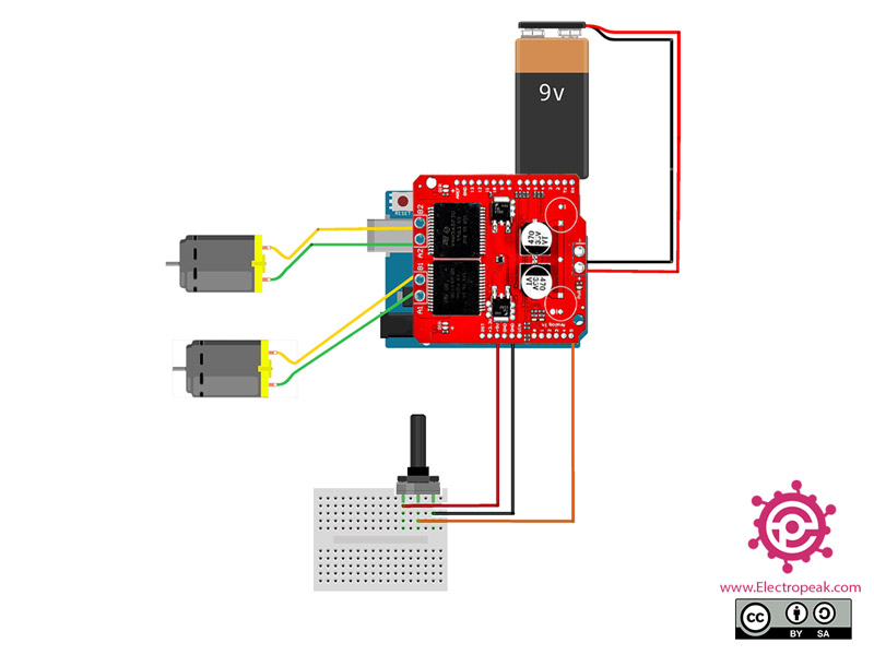
    Hi,i appreciate your answer,but i just want to know which excactly pin is needed for run a dc motor with this shield,just 2pin for digital signal and 1pin for pwm and connect gnd and vin is enough or analog pin for En1 and … So needed? I before this make a rc car with hc-05 and l298d shield and i know about hc-05 ,but when car is speedup the wire that conected to battery is melted becuse of this i wana to use this shield instead of l298d, sorry for garrulity and long text.

    April 13, 2021 at 8:41 am
    • Mehran Maleki Reply

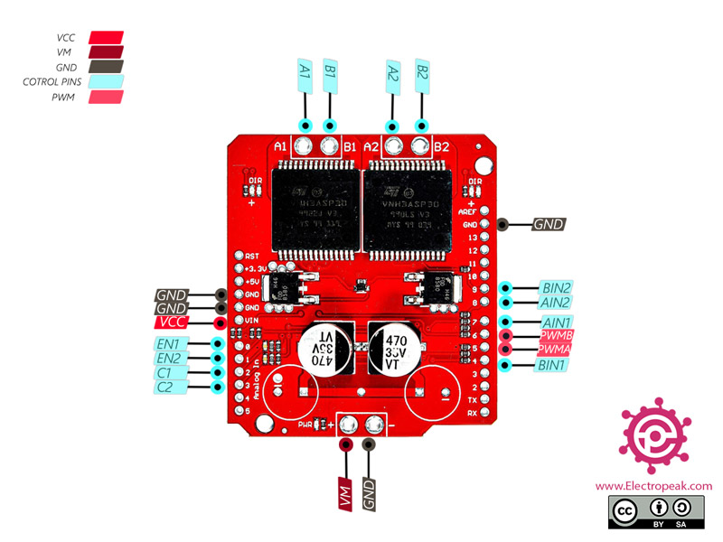
      As you can see at the beginning of the code -pin definitions-, the pins A0, A1, 4, 5, 6, 7, 8 and 9 are used to run a DC motor with this shield. And the rest of the pins are free for other uses like connecting a hc-05.

      April 14, 2021 at 5:12 am
  • سیدمحمدحسن Reply

    Thankyou,and the last my question,in the descripsion of this shield mentioned that work beetween 6to16v ,i use a 7.2v 1600ma nic,cad battery and the shield not work but when i use 9v nonrechargable battery its work,where is the wrong.

    April 14, 2021 at 6:09 am
    • Mehran Maleki Reply

      The versions of the shield might be different. And different versions may have slightly different specifications.

      April 17, 2021 at 4:37 am

Leave a Reply

Your email address will not be published. Required fields are marked *