Interfacing VNH2SP30 Monster Motor Driver with Arduino
Written by
Amir Mohammad Shojaei
VNH2SP30 Moster Motor Driver Module Features
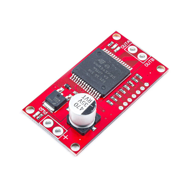
Today, speed and direction control of DC motors is very common. A Full-Bridge circuit is one of the simplest methods to control a DC motor. This module is a Full-Bridge motor driver with high output current tolerance.
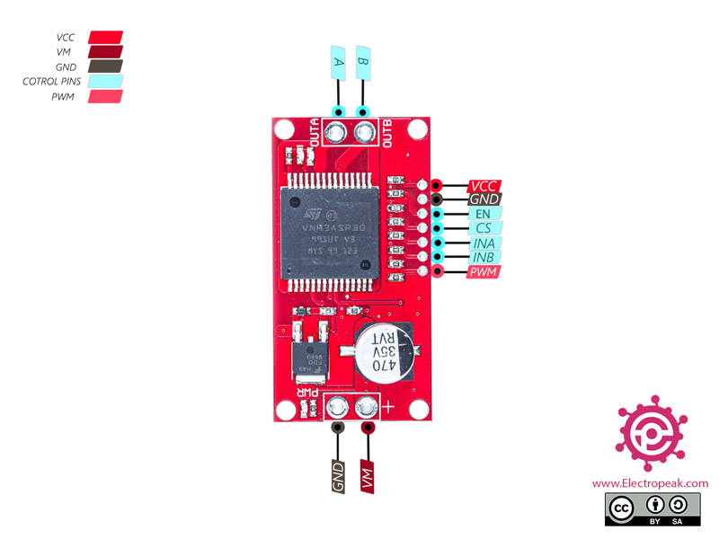
INA, INB and PWM pins are used for controlling the speed and direction of motor rotation. The CS pin is also the current sensor. This pin’s output voltage changes 0.13V per 1A.
The input voltage should be between 5.5 and 16V. Also, the maximum allowed continuous output current is 14A.
You can download the datasheet of this module here.
You can see the pinout of this module in the image below.
Note
This module can work in three mode: clockwise, counterclockwise and brake.
If INA and INB are both on or off, it is in the brake mode. If INA is on and INB is off, it is clockwise, and if INA is off and INB is on, it is counterclockwise.
Required Materials
Hardware Components
Arduino UNO R3
×
1
VNH2SP30 full-bridge Motor Driver
×
1
Micro DC Motor 6V
×
1
10 K Potentiometer
×
1
9V Battery
×
1
9V Battery Clips with Bare Leads
×
1
Male to female jumper wire
×
1
Male to Male jumper wire
×
1
400 Tie point Solderless Mini Breadboard
×
1
Software Apps
Arduino IDE
Interfacing VNH2SP30 full-bridge Motor Driver with Arduino
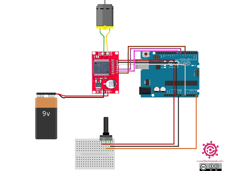
Step 1: Circuit
The following circuit shows how you should connect Arduino to VNH2SP30 module. Connect wires accordingly.
Step 2: Code
Upload the following code to your Arduino.
/*
VNH2SP30-full-bridge-Driver
made on 01 Nov 2020
by Amir Mohammad Shojaee @ Electropeak
*/
#define PWM 5
#define INA 7
#define INB 8
#define EN A0
int pot;
int out1;
void setup() {
Serial.begin(9600);
pinMode(PWM,OUTPUT);
pinMode(INA,OUTPUT);
pinMode(INB,OUTPUT);
pinMode(EN,OUTPUT);
}
void loop() {
digitalWrite(INA,HIGH); //Motor A Rotate Clockwise
digitalWrite(INB,LOW);
digitalWrite(EN,HIGH);
pot=analogRead(A5);
out1=map(pot,0,1023,0,255);
analogWrite(PWM,out1); //Speed control of Motor
}
This code is for control a DC motor’s speed. Turn the potentiometer clockwise to increases the motor’s speed. You must set the EN pin HIGHto activate the module.
Warning
Be careful not to fully turn the potentiometer because this DC motor is a 6 volts motor and the input voltage is 9 volts. So the motor may be damaged. Of course, you can use a lower voltage power supply or a higher voltage DC motor.
its working well with 20 k potenciometr. Please make code for radio control using ia6b flysky reciver and Uno there are no tutorials on this motor driver only for l298


Comment (1)
its working well with 20 k potenciometr. Please make code for radio control using ia6b flysky reciver and Uno there are no tutorials on this motor driver only for l298