
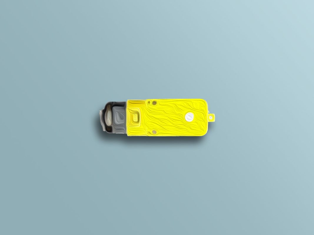
Single Axis 1:120 Gear Motor Features
If you work in electronics and robotics field, you have come across DC motors at least once. These motors are one of the most widely used elements in electronics and robotics. These motors convert direct current electrical energy into mechanical energy.
An external source provides power for the stator of these motors. As a result, the current flowing through the stator creates a uniform field under the poles. Of course, permanent magnet can supply the stator field, too. If the armature is powered by an external source or stator, a field will also be created in the armature. As the stator and armature fields interact, motor begins to rotate.
These motors are made in various voltages and speeds. If you add a gearbox to these motors, the torque will increase by reducing its speed. Here are 3 ways to control the speed of DC motors:
- Voltage control
- Current Control
- Armature resistance
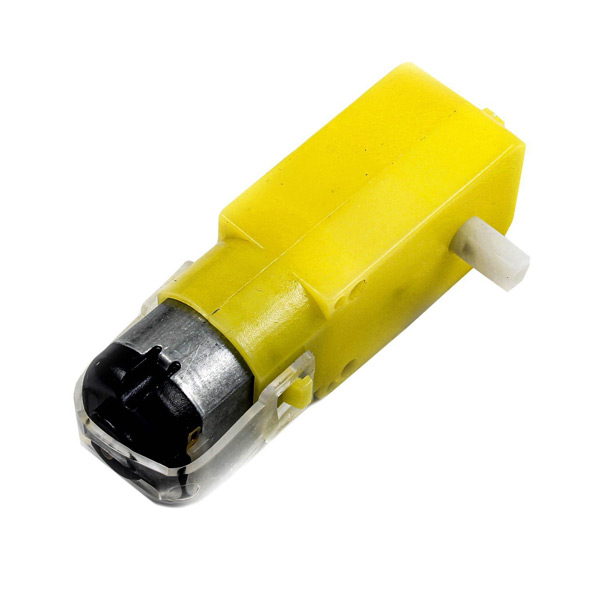
Single Axis 1:120 TT Gear Motor Pinout
These motors have two pins to connect to power supply.
Required Materials
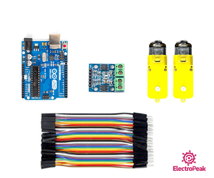
Hardware Components
Note
Software Apps
Interfacing Single Axis 1:120 TT Gear Motor with Arduino
Step 1: Circuit
The following circuit show how you should connect Arduino to this motor. Connect wires accordingly.
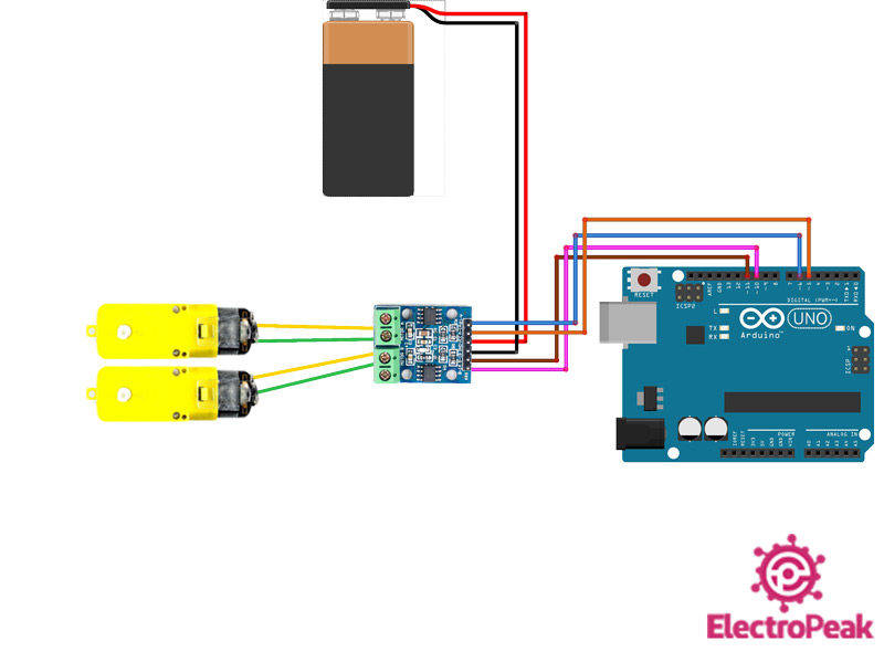
Warning
Be careful not to use a power supply higher than 6V because the maximum voltage of these motors is 6V.
Step 2: Code
Upload the following code to your Arduino.
   /*
    DC-Motor
  made on 29 Dec 2020
  by Amir Mohammad Shojaee @ Electropeak
  Home

*/

#define A1 5  // Motor A pins
#define A2 6
#define B1 10 // Motor B pins
#define B2 11

int incomingByte = 0; // for incoming serial data

void setup() {

  pinMode(A1, OUTPUT);
  pinMode(A2, OUTPUT);
  pinMode(B1, OUTPUT);
  pinMode(B2, OUTPUT);

  digitalWrite(A1, LOW);
  digitalWrite(A2, LOW);
  digitalWrite(B1, LOW);
  digitalWrite(B2, LOW);

  Serial.begin(9600); // opens serial port, sets data rate to 9600 bps

  Serial.println("select direction of movement");
  Serial.println("1.forward");
  Serial.println("2.backward");
  Serial.println("3.stop");

}
int  input = 0;
void loop() {

  // send data only when you receive data:
  if (Serial.available() > 0) {
    // read the incoming byte:
    incomingByte = Serial.read();
    input = incomingByte - 48; //convert ASCII code of numbers to 1,2,3

  switch (input) {
    case 1:         // if input=1 ....... motors turn forward
      forward();
      break;
    case 2:         // if input=2 ....... motors turn backward
      backward();
      break;
    case 3:         // if input=1 ....... motors turn stop
      Stop();
      break;
  }
  delay(200);
  input=0;
}
}
void forward() {          //function of forward
  analogWrite(A1, 255);
  analogWrite(A2, 0);
  analogWrite(B1, 255);
  analogWrite(B2, 0);
}

void backward() {         //function of backward
  analogWrite(A1, 0);
  analogWrite(A2, 210);
  analogWrite(B1, 0);
  analogWrite(B2, 210);
}

void Stop() {              //function of stop
  digitalWrite(A1, LOW);
  digitalWrite(A2, LOW);
  digitalWrite(B1, LOW);
  digitalWrite(B2, LOW);
}
This program could help you control the direction of movement through the Serial Monitor. If you enter number 1, motor rotates clockwise at maximum speed. If number 2 is entered, motor rotates counter-clockwise at a speed less than maximum. Finally, by pressing number 3, the motor will stop.
