Interfacing Piezoelectric Vibration Sensor with Arduino
Written by
Amir Mohammad Shojaei
Piezoelectric Vibration Sensor Features
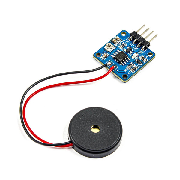
Piezoelectric vibration sensor is based on piezoelectric ceramic sheet. This sensor uses piezoelectric ceramics to generate vibration. When the piezoelectric ceramic piece vibrates, an electrical signal is generated.
This sensor has two digital and analog outputs. The greater the vibration intensity, the higher the analog output voltage. Vibration amplitude sensitivity can be adjusted by the potentiometer.
Note
When the sensor vibrates, the digital output changes from LOW to HIGH and the analog output changes from 0 to 1023 depending on the vibration intensity.
Other specifications:
Operating voltage: 5V
Potentiometer included to adjust sensitivity
Switch indicating LED
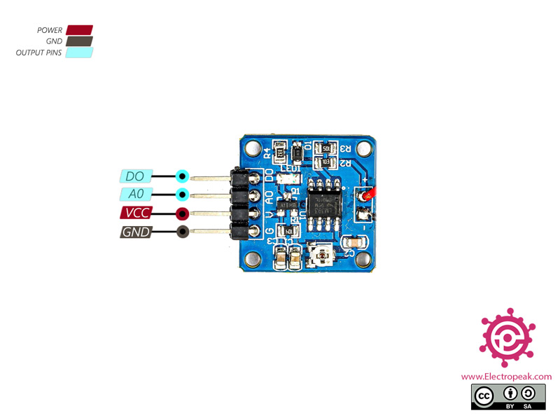
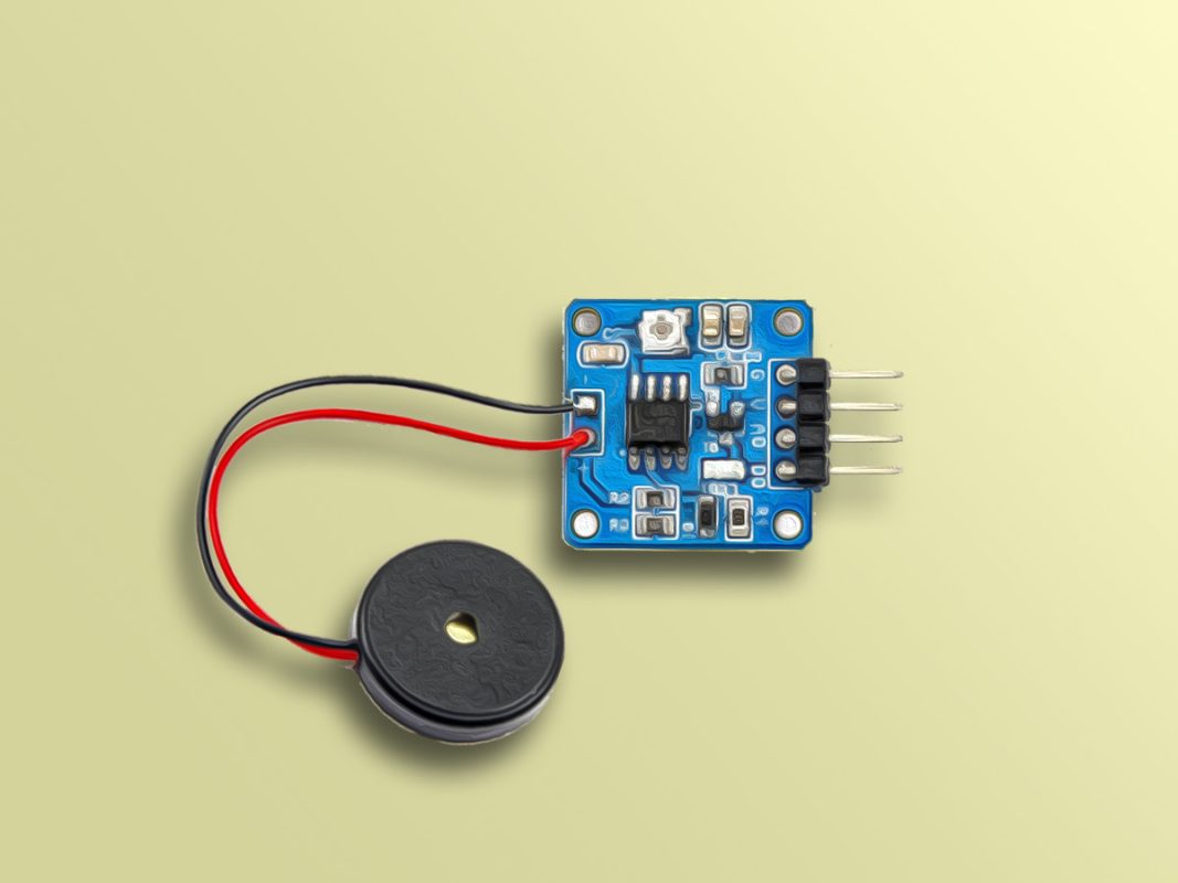
Piezoelectric Vibration Sensor Pinout
This Module has 4 pins:
VCC: Module power supply – 3.3V to 5V
GND: Ground
D0: Digital Output
A0: Analog Output
You can see the pinout of this module in the image below.
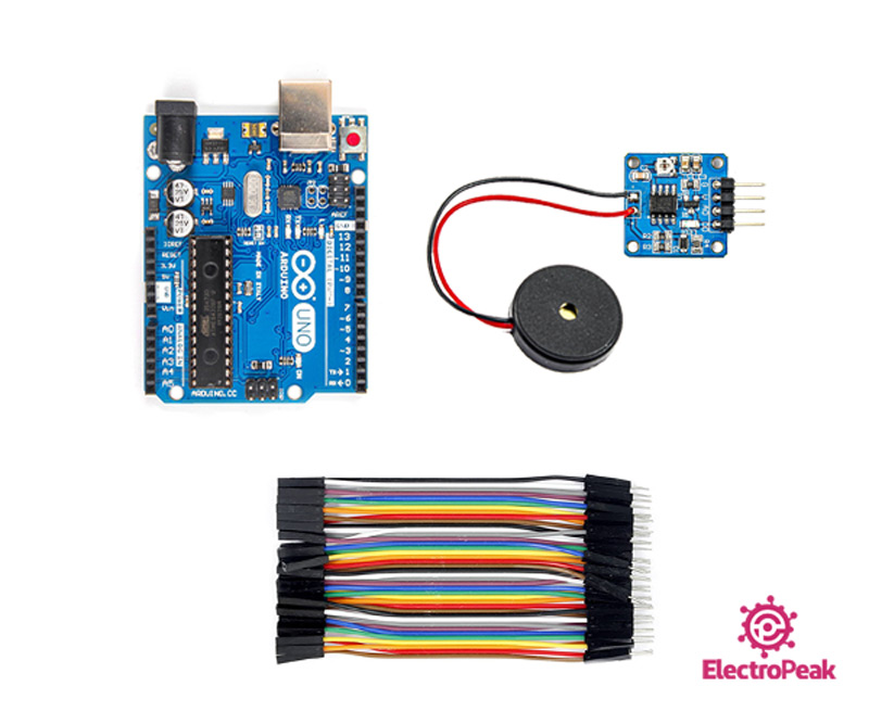
Required Material
Hardware component
آArduino UNO R3
×
1
Piezoelectric Shock Tap Sensor, Vibration Switch Module
×
1
Male to Female jumper wire
×
1
Software Apps
Arduino IDE
Interfacing Piezoelectric Vibration Sensor with Arduino
Step 1: Circuit
The following circuit show how you should connect Arduino to this sensor. Connect wires accordingly.
Step 2: Code
Upload the following code to your Arduino.
/*
Piezoelectric-Shock-Tap-Sensor-Vibration-Switch-Module
made on 05 Jan 2021
by Amir Mohammad Shojaee @ Electropeak
In this code, you can see the changes of analog and digital output pins after vibration. First, we set pin 7 as digital input and A0 as analog input and read each value. Then the values of these two pins appear on serial monitor. We have also multiplied the digital input by 100 to better see the changes.
Note
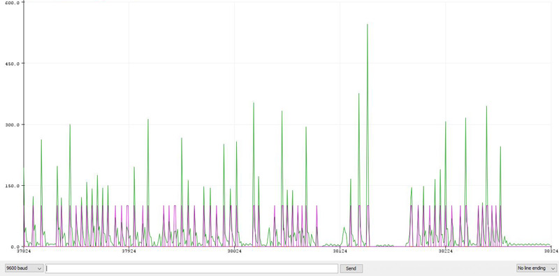
You can use the Serial Plotter to see the output changes better.
The output is as follows. The digital signal (purple) becomes HIGH by each shock or vibration, and the analog signal (green) fluctuates according to the vibration intension.


Comments (2)
the serial plotter did not work for me
Hi Josh,
Use Serial Monitor to check the value of you get from Arduino
Also u could change sensitivity of model using on board potentiometer