
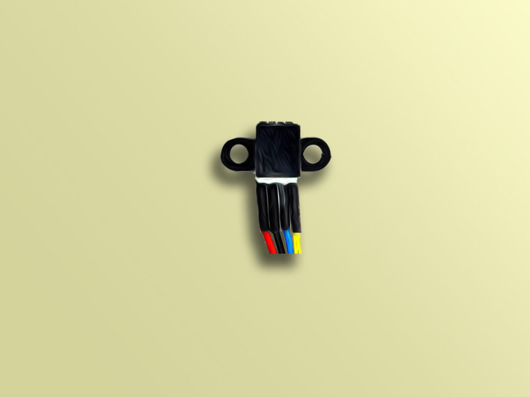
Photoelectric Encoder Module Features
Motors are used in a wide variety of applications such as robotics, industry, research and educational projects. In most of these applications, it is necessary to calculate the rotation speed, the direction of rotation and the position of the motor shaft. Rotary encoder modules can be used for this purpose. Rotary encoder is a type of module that converts rotation into electrical signals. The rotary encoder has two output pins: A and B. If the rotary encoder is installed properly, with motor rotation, electrical signals will be generated on pins A and B. By monitoring these signals, the rotation speed, the direction of rotation and position of motor can be obtained.
How it works
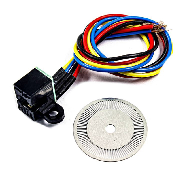
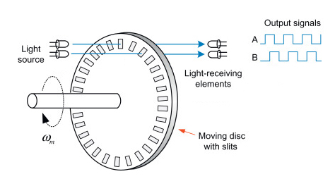
The photoelectric encoder module consists of two discs located across each other. There is a light source on one disc and two light-receiving elements (photoresistors) on the other disc. Between these disks, there is a moving disc with evenly spaced slits. By rotating this moving disc, the light receivers A and B are alternately connected and disconnected. So, a square wave will be generated at the outputs. If you count these pulses, you can calculate the amount of rotation. In addition, there is a phase difference of 90 degrees between the two outputs A and B, so we can find the direction of rotation by checking which output is ahead of the other.
Photoelectric Encoder Module Pinout
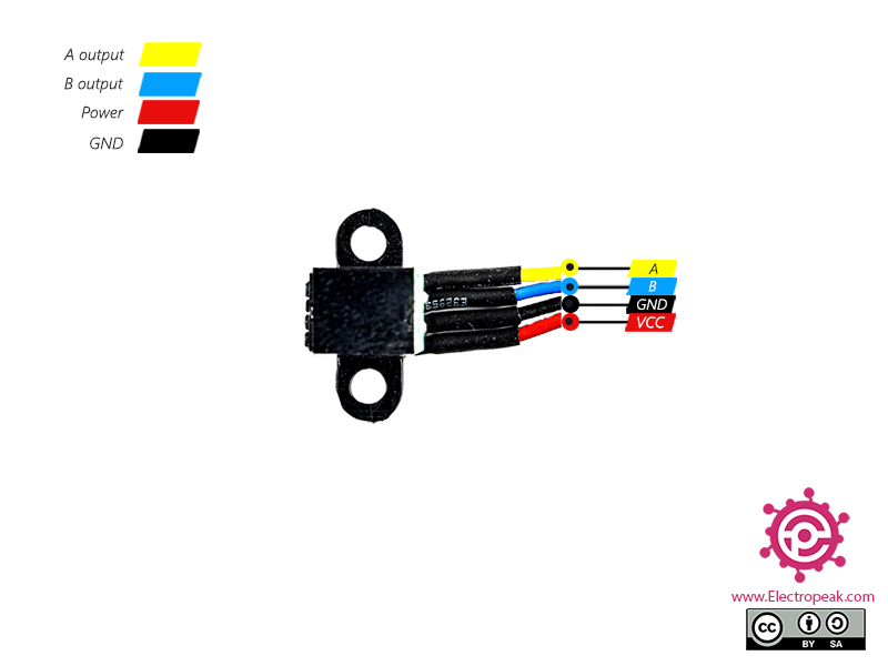
This module has 4 wires:
- output A (Yellow): Output A
- output B (Blue): Output B
- VCC (Red): Module power supply – 5V
- GND (Black): Ground
You can see the pinout of this module here.
Required Materials
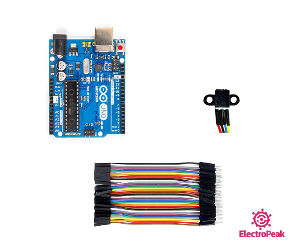
Hardware Components
Software Apps
Interfacing Photoelectric Encoder Module with Arduino
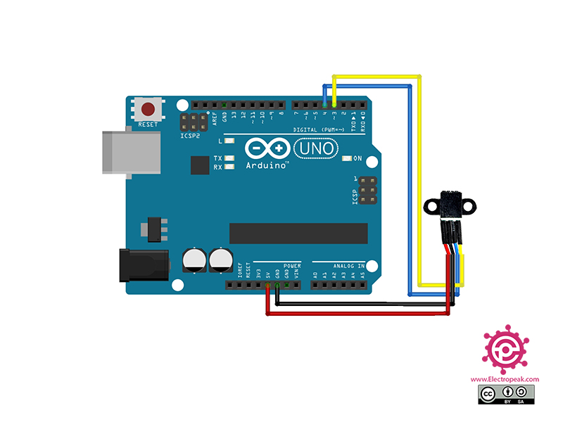
Step 1: Circuit
The following circuit shows how you should connect Arduino to this sensor. Connect wires accordingly.
Step 2: Code
Upload the following code to your Arduino. After that, open the Serial Monitor.
 /*
  Made on Jan 30, 2021
  By MehranMaleki @ Electropeak
  Home
*/

#include "Timer.h"
Timer t;

#define number_of_holes 20
#define interruptPin 3
int i = 0;

void setup() {
  pinMode(interruptPin, INPUT);
  attachInterrupt(digitalPinToInterrupt(interruptPin), counter, RISING);
  Serial.begin(9600);
  t.every(500, print_speed);
}

void loop() {
  t.update();
}


void print_speed()
{
  Serial.print("Speed:  ");
  Serial.print(i * 120 / number_of_holes);
  Serial.println(" rpm");
  i = 0;
}

void counter() {
  i++;
}
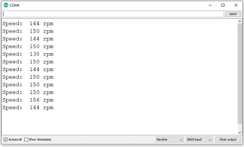
In the above code, we have calculated the number of changes in the status of output A in one minute. Then, by dividing it by the number of the rotating disc holes, we can obtain the rotation speed and display it on the Serial Monitor.
The output is as follows:

Comments (15)
in line 29, why we need to multiply with 120?
Hi my friend,
For better explanation, let me put it this way. The variable “i” is actually the number of times that the interrupt has happened at a specific period of time. And as you can see in the line 18, this specific period of time is 500 milliseconds. So, when we want to calculate the RPM (Round Per Minute) speed of the rotating disc, we need to multiply the variable “i” by 120 (1 min = 60 seconds = 500 milliseconds * 120).
Hope that’s clear! Good luck.
still i am confusing of 120 ?? , that 500 is for delay i think, timer.h shows no matching files in arudino
if don’t need 500 ms to wait for rpm , so i put in loop , what i should replace instead of 120
Hi,
You can see a full explanation of the code in the reply to the previous comment. That is related to the use of “120” and can help you get over your confusion.
In overall, to calculate the RPM (Round Per Minute) of a rotating disc, you need to count the number of rotations (Round) in every 60 seconds (1 minute).
In this code, we have counted the number of rotations in every 500 milliseconds, so, we need to multiply it by 120 to calculate the number of rotations in every 60 seconds.
If, for any reason, you want to change 500 ms to X ms, you need to replace “120” with “60000 / X”.
thnkq for your work its working because of your explanation
You’re quite welcome! Glad it worked.
can we program it for see the motor rotation direction , when i use to interrupt it always show clockiwse direction even i rotation in anticlockwise,
Yes, that’s also possible. As stated in the article, all rotary encoders have 2 outputs: A & B. There is a phase difference of 90 degrees between these two outputs, so we can find the direction of rotation by checking which output is ahead of the other.
Here in this tutorial, we have used only one of the outputs since one of them is enough for calculating the speed of rotation. To see how to use them both and figure out the direction, you can check the following tutorial:
“https://electropeak.com/learn/rotary-encoder-how-it-works-how-to-use-with-arduino/”
there is an issue with the included library “TIMER”, the library actually is not recognised and if i use TimerOne, how am supposed to declare t? an answer would be very helpful
Hi,
As long as I know, there is nothing wrong with the “Timer” library. What actually might have caused the problem is that you already have some other timer libraries installed on your Arduino IDE, and they’re causing conflicts with the “Timer” library, so it can’t work properly. One thing you could do is to delete any timer library you have and just install the “Timer” library of this article. That would solve your problem. But anyway, if you prefer to use the “TimerOne” library, you can take a look at its examples to see how you can use it. You can find its examples in Arduino IDE, File → Examples → TimerOne.
Hi Mehran,
Maybe it’s possible to explain why you define 20 holes while the coded disk has 100 holes.
There is a logic story behind it but it could make fiddling with this kind of sensors a whole lot easier.
Hi,
Sorry for the delay in response. Well, the disk I used while doing this project had 20 holes, so I defined holes to be 20. If you have a disk with a different number of holes, you can just change line 10 of the code accordingly.
hi i will so thank full if you reply me i used this code for Optical encoder but i recieved this reaction speed 0 rpm
Hi zahra,
Your data will remain 0 until there is a movement on the shaft side or on the encoder.
You can use this code to test your component.
volatile long counter = 0;

void A() {

  if (digitalRead(21) == LOW) {

    counter++;

  } else {

    counter--;

  }

}
void B() {
if (digitalRead(20) == LOW) {
counter--;
} else {
counter++;
}
}
void setup()
{
Serial.begin(115200);
pinMode(20, INPUT_PULLUP);
pinMode(21, INPUT_PULLUP);
attachInterrupt(digitalPinToInterrupt(20), A, RISING);
attachInterrupt(digitalPinToInterrupt(21), B, RISING);
}
void loop(){
if ( counter != x ) {
Serial.println (counter);
x = counter;
}
}