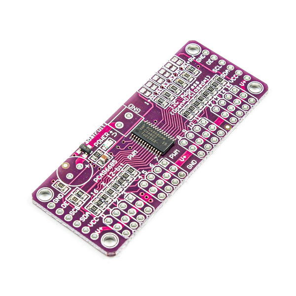
PCA9685 16 Channel 12-bit PWM Driver Features
PCA9685 16-Channel module is very useful and can help a lot when there are insufficient PWM output pins. The most important application is to control servo motors. This module can control a large number of servo motors at the same time.
As mentioned, the PCA9685 driver can be used to control 16 servo motors. In fact, this module only uses the I2C pins of the microcontroller. You can even connect 62 of these modules together to get up to 992 PWM outputs using only the same two I2C pins.
Other features:
- Adjustable frequency PWM up to about 1.6 kHz
- 12-bit Resolution for each output
We use MG-995 servo motor to interface this module. The applied voltage of this motor should be in range of 4.8 to 7.2V. The frequency of motor is 50 Hz and the PWM duty cycle is 20 milliseconds. This motor has 3 pins as follows:
- PWM: Orange
- VCC: Red
- GND: Brown
You can download the datasheet of PCA9685 here.
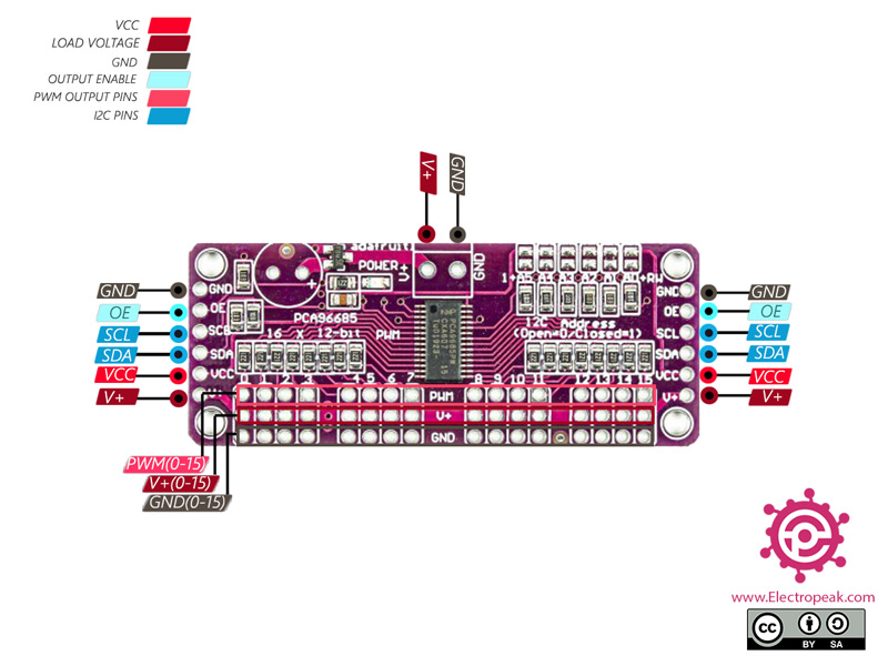
PCA9685 16 Channel 12-bit PWM Driver Pinout
This Module has 16 pins:
Power pins:
- VCC: Module power supply
- GND: Ground
- V+: Servo motor power supply – The voltage should be 5-6V.
- IN2: control pin 2
Control pins:
- SCL: I2C clock
- SDA: I2C Data
- OE: Output activation pin – If this pin is HIGH, the module outputs are disabled.
Output pins:
- PWM: PWM output
- V+: Output power supply
- GND: Ground
Warning
VCC voltage is for module power supply only. If you are using a servo motor or LED at output, connect the V+ to appropriate power supply.
You can see the pinout of this motor in the image below.
Required Material
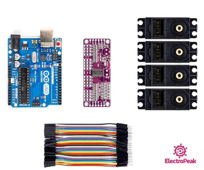
Hardware component
Software Apps
Note
For this tutorial, you can prepare a desired number up to 16 servo motors.
In this tutorial, we have used 4 servo motors.
Interfacing PCA9685 16 Channel 12-bit PWM Servo Driver with Arduino
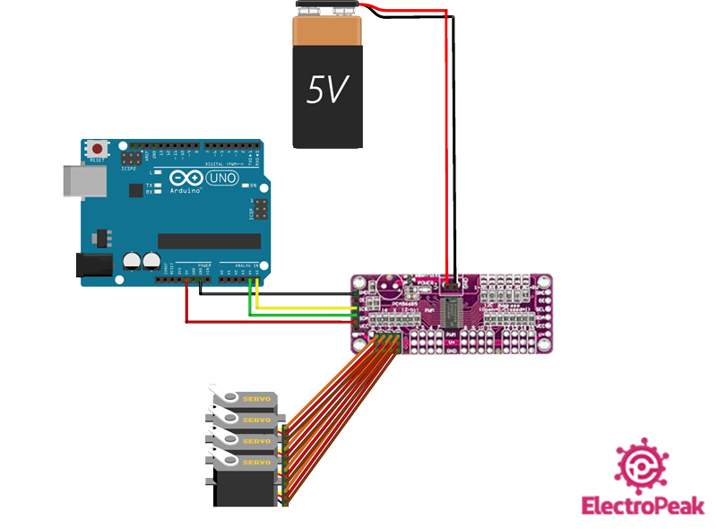
Step 1: Circuit
The following circuit show how you should connect Arduino to PCA9685 module. Connect wires accordingly.
Warning
Be careful not to use power supply greater than the motor voltage, since the operating voltage is 5-6V.
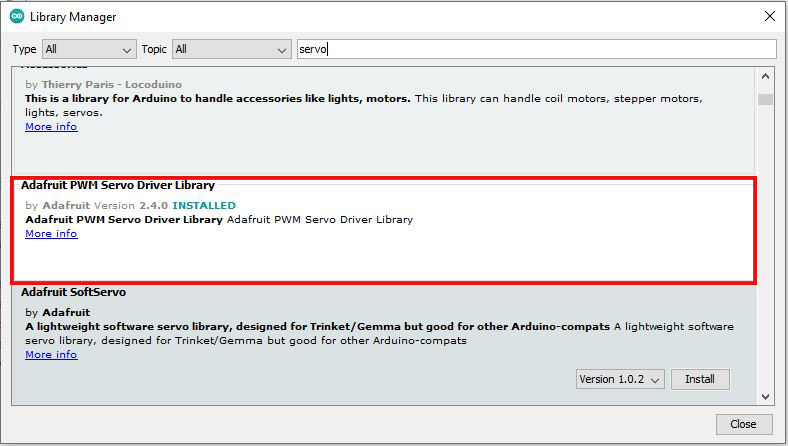
Step 2: Library
Go to Library manager and search for Servo and then install Adafruit PWM Servo Driver Library as shown below.
Tip
If you need more help with installing a library on Arduino, read this tutorial: How to Install an Arduino Library
Step 3: Code
Upload the following code to your Arduino.
/*
PCA9685-16Channel-12bit-PWM-Servo-Driver
modified on 16 Dec 2020
by Amir Mohammad Shojaee @ Electropeak
Home
based on Arduino - Adafruit library
*/
#include <Wire.h>
#include <Adafruit_PWMServoDriver.h>
// called this way, it uses the default address 0x40
Adafruit_PWMServoDriver pwm = Adafruit_PWMServoDriver();
#define SERVOMIN 150 // This is the 'minimum' pulse length count (out of 4096)
#define SERVOMAX 600 // This is the 'maximum' pulse length count (out of 4096)
#define USMIN 600 // This is the rounded 'minimum' microsecond length based on the minimum pulse of 150
#define USMAX 2400 // This is the rounded 'maximum' microsecond length based on the maximum pulse of 600
#define SERVO_FREQ 50 // Analog servos run at ~50 Hz updates
// our servo # counter
uint8_t servonum = 0;
void setup() {
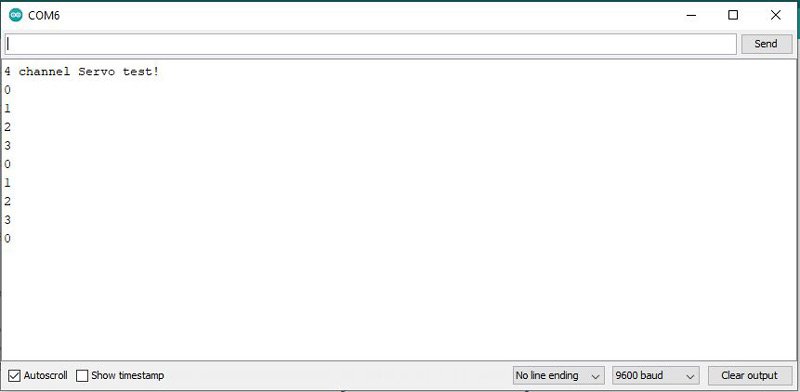
Serial.begin(9600);
Serial.println("4 channel Servo test!");
pwm.begin();
pwm.setOscillatorFrequency(27000000);
pwm.setPWMFreq(SERVO_FREQ); // Analog servos run at ~50 Hz updates
delay(10);
}
// You can use this function if you'd like to set the pulse length in seconds
// e.g. setServoPulse(0, 0.001) is a ~1 millisecond pulse width. It's not precise!
void setServoPulse(uint8_t n, double pulse) {
double pulselength;
pulselength = 1000000; // 1,000,000 us per second
pulselength /= SERVO_FREQ; // Analog servos run at ~60 Hz updates
Serial.print(pulselength); Serial.println(" us per period");
pulselength /= 4096; // 12 bits of resolution
Serial.print(pulselength); Serial.println(" us per bit");
pulse *= 1000000; // convert input seconds to us
pulse /= pulselength;
Serial.println(pulse);
pwm.setPWM(n, 0, pulse);
}
void loop() {
// Drive each servo one at a time using setPWM()
Serial.println(servonum);
for (uint16_t pulselen = SERVOMIN; pulselen < SERVOMAX; pulselen++) {
pwm.setPWM(servonum, 0, pulselen);
}
delay(500);
for (uint16_t pulselen = SERVOMAX; pulselen > SERVOMIN; pulselen--) {
pwm.setPWM(servonum, 0, pulselen);
}
delay(500);
servonum++;
if (servonum > 3) servonum = 0; // Testing the first 4 servo channels
}
At the beginning of this code, the two required libraries are included. The following is the data related to servo motor. Then, in the main loop of code, each stepper motor rotates 180 degrees clockwise and 180 degrees counter-clockwise, respectively. Just be careful if you use more or less than 4 servo motors, change the number in the last line of code.
The output is as follows. When each servo motor rotates, its number appears on series monitor.