Interfacing MCP23017-E/SS 16-Channel I/O Expansion Module with Arduino
Written by
Mehran Maleki
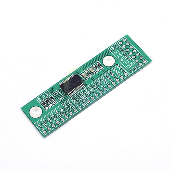
MCP23017-E/SS 16-Channel I/O Expansion Module Features
The MCP23017-E/SS 16-Channel I/O expansion module is used in projects that require a large number of input-output pins. This development board communicate to the microcontroller using I2C interface and increases the number of input-output pins of microcontroller. The added pins can be easily set as input, output and interrupt.
*/
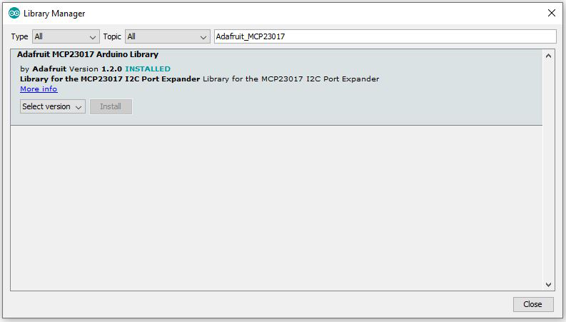
#include <Wire.h>
#include "Adafruit_MCP23017.h"
// Basic pin reading and pullup test for the MCP23017 I/O expander
// public domain!
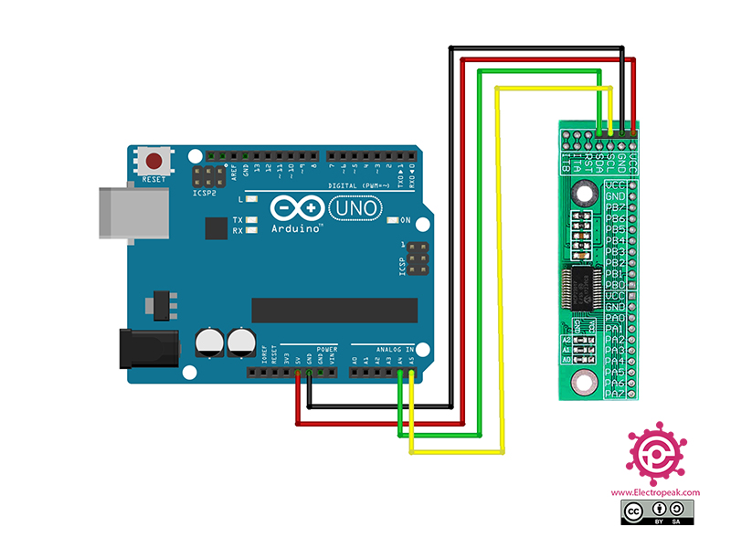
// Connect pin #12 of the expander to Analog 5 (i2c clock)
// Connect pin #13 of the expander to Analog 4 (i2c data)
// Connect pins #15, 16 and 17 of the expander to ground (address selection)
// Connect pin #9 of the expander to 5V (power)
// Connect pin #10 of the expander to ground (common ground)
// Connect pin #18 through a ~10kohm resistor to 5V (reset pin, active low)
// Output #0 is on pin 21 so connect an LED or whatever from that to ground
Adafruit_MCP23017 mcp;
void setup() {
mcp.begin(); // use default address 0
mcp.pinMode(0, OUTPUT);
Serial.begin(9600);
}
// flip the pin #0 up and down
void loop() {
int x;
mcp.digitalWrite(0, HIGH);
x = mcp.digitalRead(0);
int i;
for(i = 0; i < 40; i++) {
Serial.println(x);
delay(50);
}
mcp.digitalWrite(0, LOW);
x = mcp.digitalRead(0);
for(i = 0; i < 40; i++) {
Serial.println(x);
delay(50);
}
}
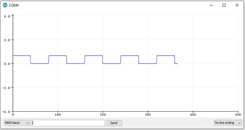
In this code, pin PA0 (pin zero of MCP23017-E/SS board) is set as output and will be High and Low alternately. The value appears on Serial Plotter.