Interfacing L298P H-bridge Motor Driver Shield with Arduino
Written by
Amir Mohammad Shojaei
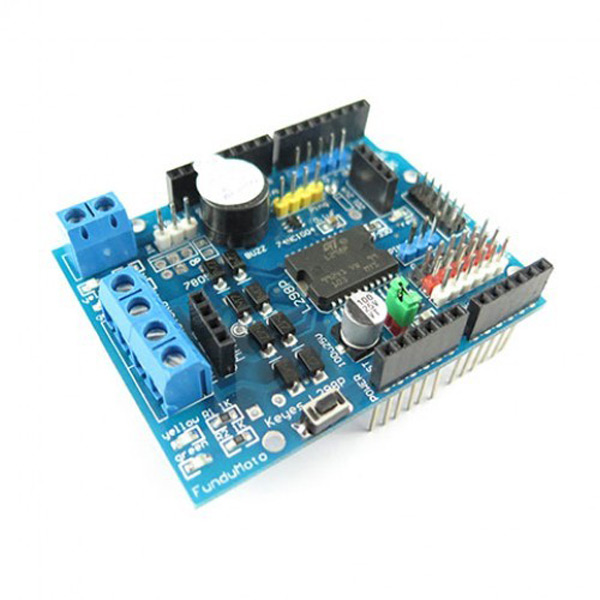
L298P Motor Driver Shield Features
Today, DC motors are used in the manufacturing many tools and equipments. So, speed and direction control of these motors is very common.
A half-bridge circuit is one of the simplest methods to control a DC motor. This method not only controls the motor direction, but also can be used for speed control. This shield is based on L298P IC.
The most important features are:
Control two DC motors simultaneously with voltage 4.8 to 24V and up to 2A current
Schottky diodes to protect against reverse motor voltage
Drive a servo motor with a dedicated voltage regulator
Buzzer to make sound
Bluetooth connections
6 digital and analog pins with 5V and GND pins for easy connection
Special pins for connection to ultrasonic sensor
You can download the datasheet of this module here.
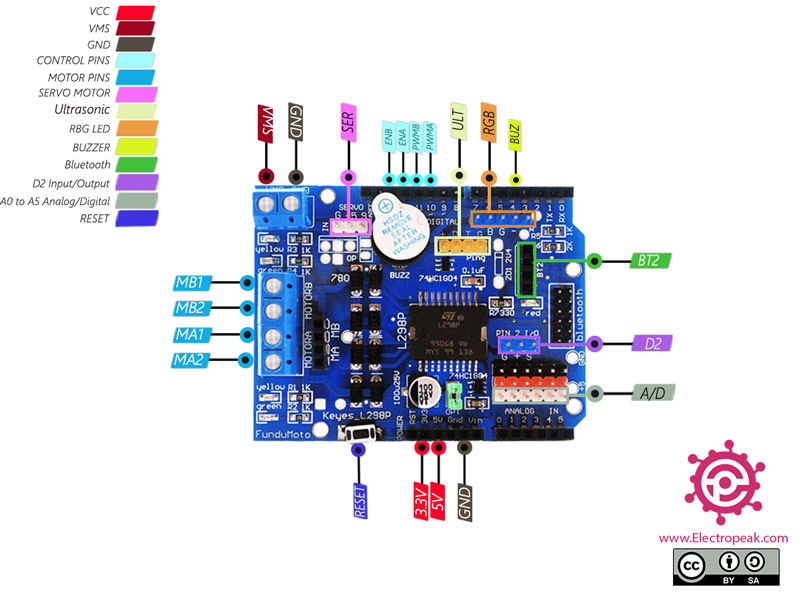
This motor shield has various connection as follows:
Control of two DC motors connections:
VMS: Module voltage
GND: Ground
MA1: Positive end for motor A
MA2: Negative end for motor A
MB1: Positive end for motor B
MB2: Negative end for motor B
PWMA: Speed control signal for motor A – This pin is connected to pin 10 of Arduino
PWMB: Speed control signal for motor B – This pin is connected to pin 11 of Arduino
ENA: Control signal for motor A – If HIGH, motor is in direct mode and if LOW, motor is rotating in reverse. This pin is connected to pin 12 of Arduino
ENB: Control signal for motor B – If HIGH, motor is in direct mode and if LOW, motor is rotating in reverse. This pin is connected to pin 13 of Arduino
Buzzer for make sound:
BUZ: Buzzer pin – This pin is connected to pin 4 of Arduino
Connection for control servo motor:
SER: PWM pin for control servo motor – This pin is connected to pin 9 of Arduino
Bluetooth connections:
BT2: Bluetooth Pins including +(3.3V) pins, (GND), RX (connected to D0) and TX (connected to D1)
Ultrasonic sensor connection:
ULT: connection pins to ultrasonic sensor including +(5V), (GND), Return (connected to D9) and Trigger (connected to D8)
RBG LED connection:
RGB: RGB: For connection to RGB LED including pins B (connected to D6), G (connected to D5) and R (connected to D3)
Other connections:
A/D: Analog and digital pins A0 to A5 for sensor and module use
D2: Digital pin 2 for sensor and module use
RS: Reset pin
GND: Ground
VCC: Board power supply – 3V, 5V
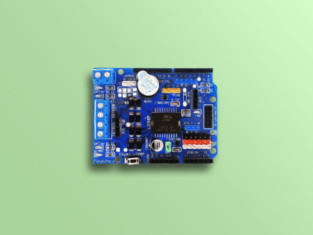
You can see the pinout of this module in the image below.
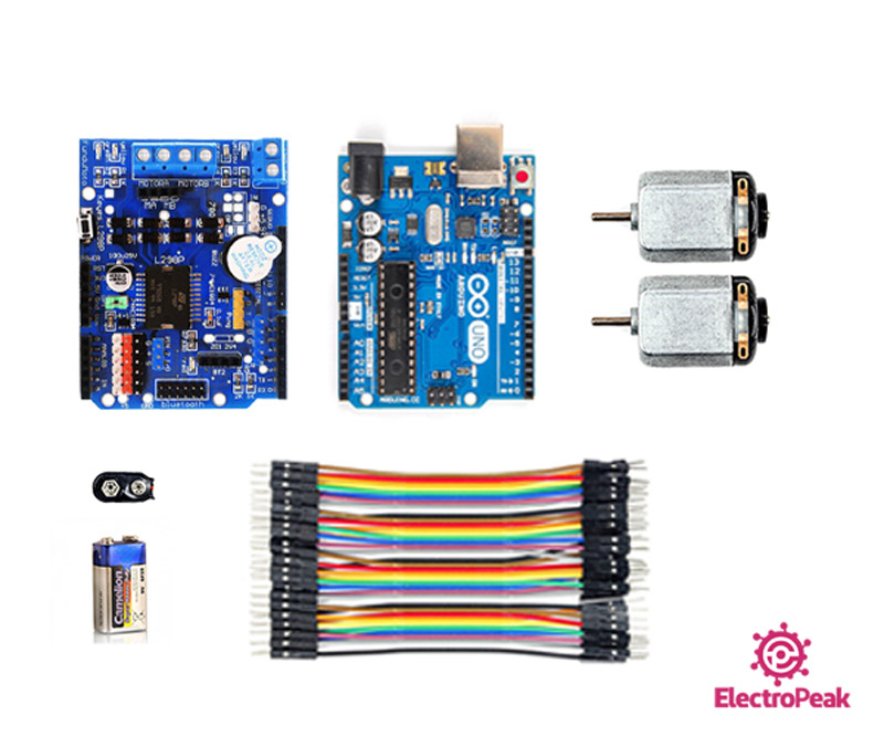
Required Materials
Hardware Components
Arduino UNO R3
×
1
L298P Motor Driver Shield
×
1
Micro DC Motor 6V
×
2
9V Battery
×
1
9V Battery Clips with Bare Leads
×
1
Male to Male Jumper wire
×
1
Software Apps
Arduino IDE
Interfacing L298P Motor Driver Shield with Arduino
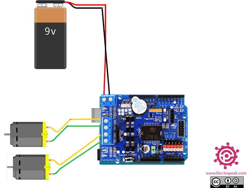
Step 1: Circuit
First, place the shield directly on the Arduino. Connect other parts to the shield accordingly.
Step 2: Code
Upload the following code to your Arduino.
/*
L298P-Motor-Driver-Shield
made on 09 Nov 2020
by Amir Mohammad Shojaee @ Electropeak
*/
int pwmA = 10;
int pwmB = 11;
int enA = 12;
int enB = 13;
int buz = 4;
void setup() {
pinMode(pwmA, OUTPUT);
pinMode(pwmB, OUTPUT);
pinMode(enA, OUTPUT);
pinMode(enB, OUTPUT);
pinMode(buz, OUTPUT);
}
void loop() {
for (int x = 50; x < 200; x++) {
digitalWrite(enA, HIGH);
digitalWrite(enB, HIGH);
analogWrite(pwmA, x);
analogWrite(pwmB, x);
delay(10);
}
for (int y = 200; y > 50; y--) {
digitalWrite(enA, HIGH);
digitalWrite(enB, HIGH);
digitalWrite(buz, HIGH);
analogWrite(pwmA, y);
analogWrite(pwmB, y);
delay(1);
}
digitalWrite(buz, LOW);
delay(1000);
}
This code is for controlling two DC motors simultaneously. First, the speed of the two engines increases. Then their speed is reduced to zero. During the deceleration, the buzzer is turned on to make sound.
Hi, what code would you use to stop the motors if you were controlling them with a joystick, i have tried different things including setting the pwm to zero, making it slow down first, and even setting pwm pins to digital low, but nothing works, the motors just move at free will at a particular direction when no command is being sent, even though they do listen to commands.
Hi.
Setting the pins to digital Low might not work after you have used the “analogWrite” command for them. Try “analogWrite(pin, 0)” to see if it makes any difference.


Comments (5)
Hi, what code would you use to stop the motors if you were controlling them with a joystick, i have tried different things including setting the pwm to zero, making it slow down first, and even setting pwm pins to digital low, but nothing works, the motors just move at free will at a particular direction when no command is being sent, even though they do listen to commands.
Hi.
Setting the pins to digital Low might not work after you have used the “analogWrite” command for them. Try “analogWrite(pin, 0)” to see if it makes any difference.
Thanks, i ended up figuring out, i had to initialize them to a stop by setting them all low.
Setting the pwm pins to 0 or digital low in the setup*
Yes, that’s the right way to do it.