Interfacing L298N Motor Driver Module with Arduino
Written by
Saeed Olfat
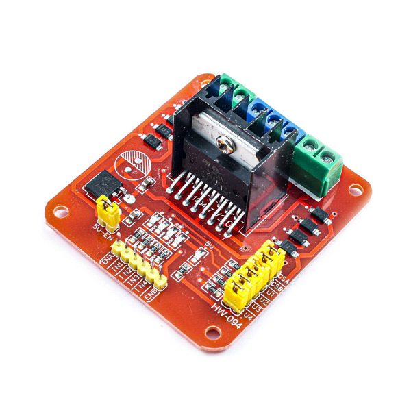
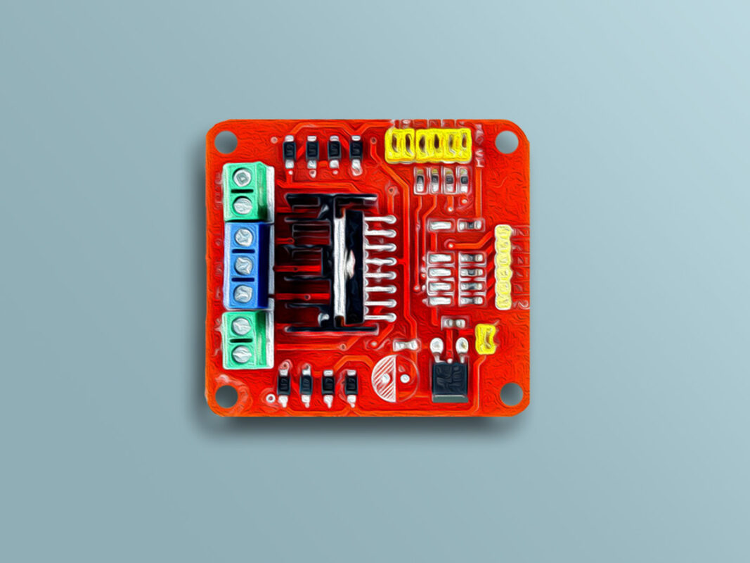
L298N Motor Driver Module Features
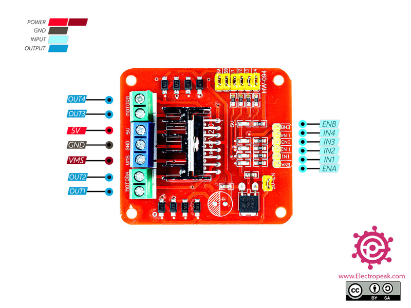
The L298N module is used to drive DC motors with a maximum current of 2 amps. The L298N driver module is easy to use. It contains a good filter circuit and gives you access access to inputs and outputs via pin headers and terminals.
The L298N is a dual full-bridge motor driver that allows two DC motors to be connected simultaneously.
Note
The L298N motor controller follows the H-bridge configuration, which is handy to drive a stepper motors.
This driver needs a logic voltage supply to drive the motors, which uses a 5-volt regulator to solve the logic voltage supply problem. This module features:
Max operating voltage: 46 V DC
Max output current: 2 A (Peak 3 A)
Power: 25 W
Input voltage level: 5 V
Working temperature: -25 to 130 Celsius
Note
If the load on the motor is high, the driver temperature will rise rapidly. S Since the working temperature of the L298N is between -25 and 130 degrees Celsius, heatsink should be used to cool down the module.
You can download the datasheet of this module here.
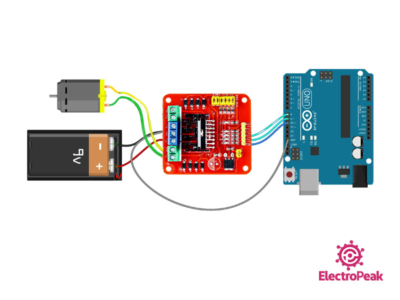
As you can see in the code, the motor first moves forward for 3 seconds and backward for 3 seconds. Then the motor stops and its speed increases from 0 to 100% in the forward direction with constant acceleration, and then the same movement is done in reverse.
Hello. I built the circuit as you said and set it up with the same code. But my DC motor did not work. After that, I connected the motor pins directly to the VMS and GND ports and the motor worked. Is there a problem with my board?
my Supply: 9V-1A


Comments (2)
Hello. I built the circuit as you said and set it up with the same code. But my DC motor did not work. After that, I connected the motor pins directly to the VMS and GND ports and the motor worked. Is there a problem with my board?
my Supply: 9V-1A
Hi oveas,
did you connect the GND pins of all components together?