Interfacing H5V4D 433MHz RF Receiver Module with Arduino
Written by
Mohammad Damirchi
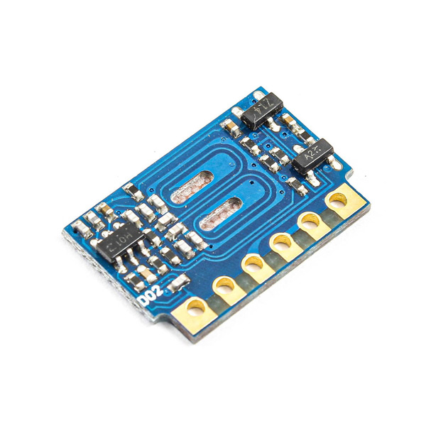
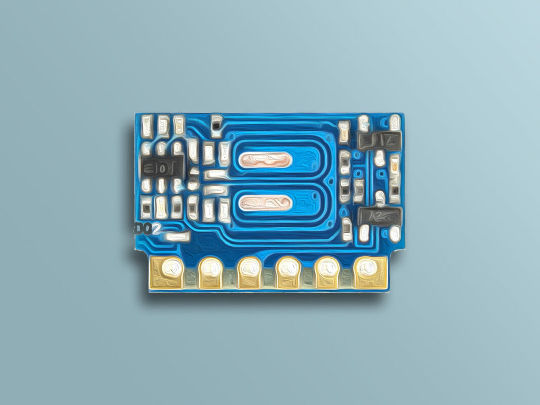
H5V4D RF Receiver Module Features
Electronic devices need to be connected wirelessly in so many cases. In these cases, Radio Frequency or RF equipments are often used. RF modules include all radio waves that can travel different distances and reach the receiver according to their frequency and amplitude.
This module is only produced at 433MHz.
Note
All modules that use the 315/433MHz frequency band can communicate with each other and there is no information security in this type of communication. If you need security, you must use encryption (locking) on the receiver and transmitter.
Note
This module only receives information but cannot send them. So, on the transmitter side, we have used a type of radio transmitter according to the receiver frequency.
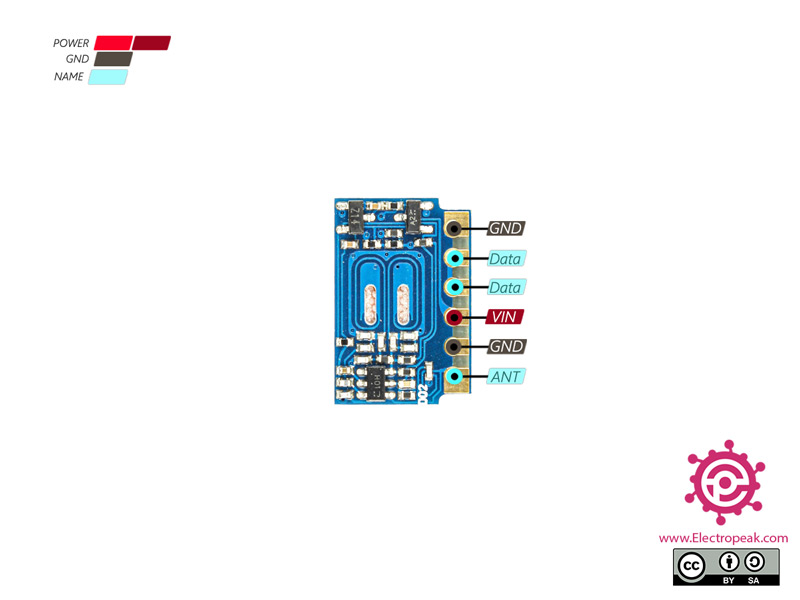
H5V4D RF Receiver Module Pinout
This module has 4 pins:
VIN: Module power supply
GND: Ground
Data: Data line for sending or transmitting
ANT: Antenna (It’s optional)
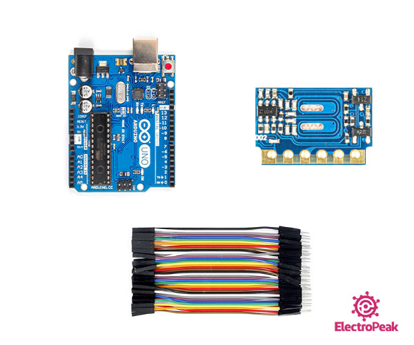
Required Materials
Hardware Components
Arduino UNO R3
×
1
H5V4D 433MHz Wireless Receiver Module
×
1
male-female-jumper-wire
×
1
Software Apps
Arduino IDE
Interfacing H5V4D RF Receiver Module with Arduino
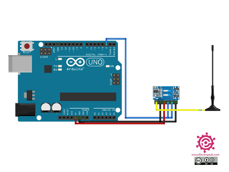
Step 1: Circuit
The following circuit shows how you should connect the Arduino Board to the H5V4D module. Connect wires accordingly.
Step 2: Library
Install the following library on your Arduino IDE.