Contents

Interfacing GY-521 MPU6050 3-Axis Accelerometer Gyroscope with Arduino

GY-521 MPU6050 Features

The GY-521 is based on the MPU6050 sensor that contains both a 3-Axis Gyroscope and a 3-Axis accelerometer. It uses I2C communication protocol and you can read MPU6050 outputs with SCL and SDA pins.

Note

The MPU6050 sensor has a digital thermometer in addition to the gyroscope and accelerometer.

You can download the datasheet of this module here.

GY-521 MPU6050 Sensor Pinout

This sensor has 8 pins:

  • VCC: Module power supply – 3-5 V
  • GND: Ground
  • SCL: I2C Clock
  • SDA: I2C data
  • XDA: Auxiliary I2C Data
  • XCL: Auxiliary I2C Clock
  • ADO: Adjusting I2C Address
  • INT: Interrupt

You can see pinout of this module in the image below.

Required Materials

Hardware Components

Arduino UNO R3 × 1
MPU6050 Accelerometer Gyroscope Module × 1
Male to Female jumper wire × 1

Software Apps

Arduino IDE

Interfacing GY-521 MPU6050 Module with Arduino

Step 1: Circuit

The following circuit shows how you should connect Arduino to MPU6050 module. Connect wires accordingly.

Step 2: Installing Library

Go to Library manager and install the MPU6050 sensor library.

Tip

If you need more help with installing a library on Arduino, read this tutorial: How to Install an Arduino Library

Step 3: Code

Upload the following code to your Arduino. This code displays the output of the gyroscope sensor and accelerometer in the serial monitor. You can also use the Serial plotter to plot output data.

    /*
  GY-521 (MPU6050) 3-Axis Accelerometer-Gyroscope Sensor
  modified on 28 Sep 2020
  by Mohammad Reza Akbari @ Electropeak
  
Home
Based on Adafruit Example */ #include <Adafruit_MPU6050.h> #include <Adafruit_Sensor.h> #include <Wire.h> Adafruit_MPU6050 mpu; void setup(void) { Serial.begin(115200); while (!Serial) { delay(10); // will pause Zero, Leonardo, etc until serial console opens } // Try to initialize! if (!mpu.begin()) { Serial.println("Failed to find MPU6050 chip"); while (1) { delay(10); } } mpu.setAccelerometerRange(MPU6050_RANGE_16_G); mpu.setGyroRange(MPU6050_RANGE_250_DEG); mpu.setFilterBandwidth(MPU6050_BAND_21_HZ); //Serial.println(""); delay(100); } void loop() { sensors_event_t a, g, temp; mpu.getEvent(&a, &g, &temp); Serial.print("Temperature:"); Serial.print(temp.temperature); Serial.print("\tx-acceleration:"); Serial.print(a.acceleration.x); Serial.print("\ty-acceleration:"); Serial.print(a.acceleration.y); Serial.print("\tz-acceleration:"); Serial.print(a.acceleration.z); Serial.print("\tx-gyro:"); Serial.print(g.gyro.x); Serial.print("\ty-gyro:"); Serial.print(g.gyro.y); Serial.print("\tz-gyro:"); Serial.println(g.gyro.z); delay(10); }

After running the code, you will see the following image in the serial output.

Liked What You See?​
Get Updates And Learn From The Best​

Comments (2)

  • Amal Koshy Reply

    Hey, what unit does it calculate acceleration in? m/s^2 or G’s.

    December 5, 2023 at 4:23 pm
    • Mohammad Damirchi Reply

      Hi Amal,
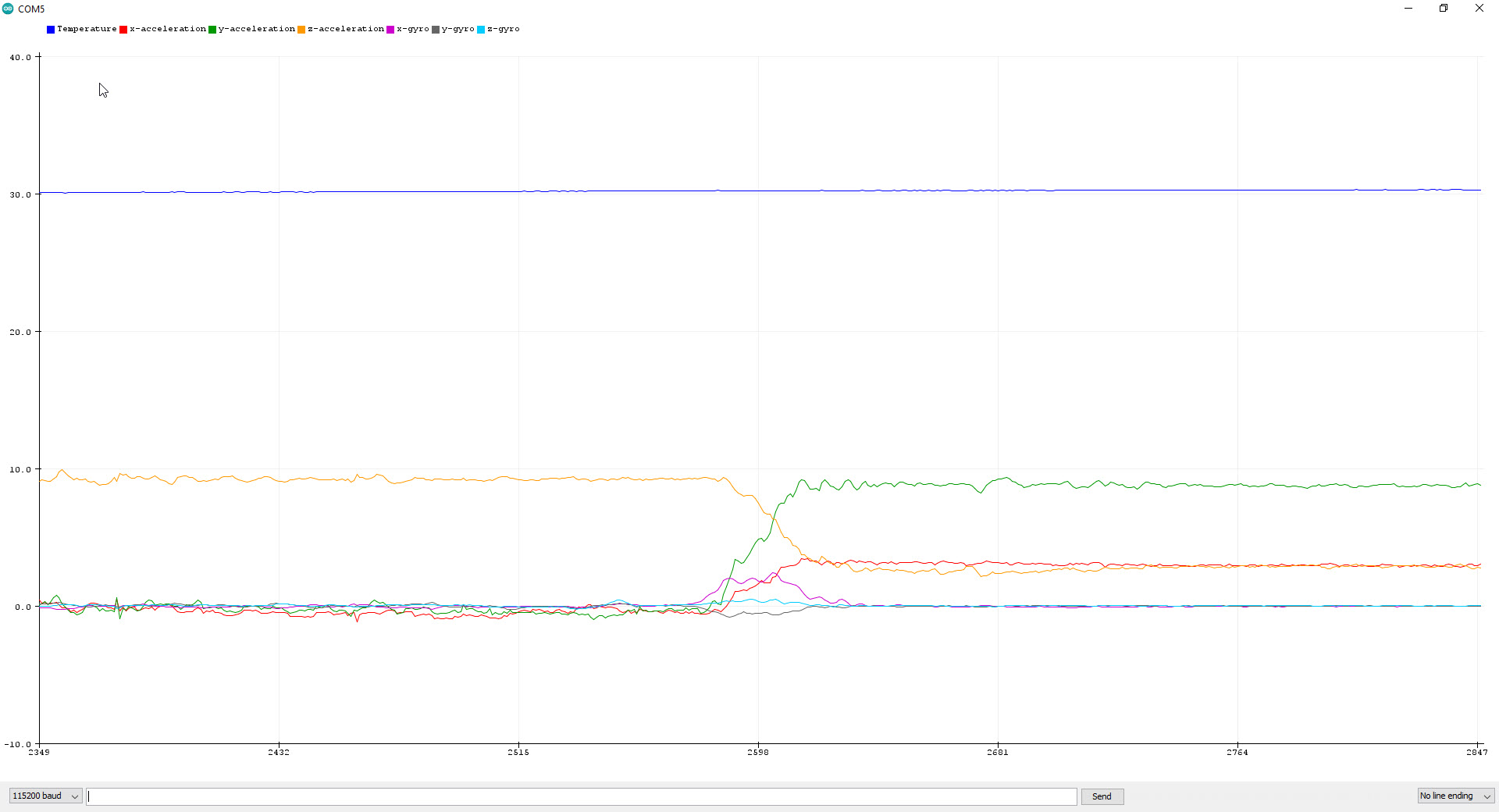
      Accelerometer sensors have the ability to adjust the measurement range. For example, you can choose a number from 2g to 16g.
      On the other hand, your output is of binary number type. For example, if your sensor is 12-bit, and you set the range to +-2g, it will output 4096 at acceleration 2g. You have to multiply this number by the factor called “sensitivity” in the datasheet to get the acceleration value.
      In some accurate and expensive accelerometers such as ADIS16488, the measurement range is fixed, and by multiplying the sensitivity by the output number, the acceleration in g units is obtained.

      December 6, 2023 at 6:26 am

Leave a Reply

Your email address will not be published. Required fields are marked *