
Product added to cart

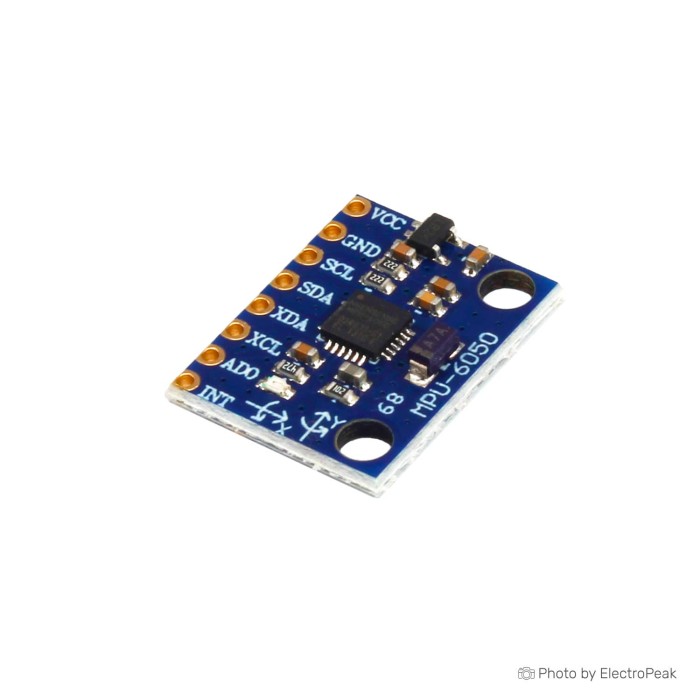
GY-521 MPU6050 3-Axis Accelerometer Gyroscope Module
$1.9600
In stock
SKU
SEN-03-004
Volume discounts:
- +50 4 % $1.8800
- +100 6 % $1.8400
- +300 8 % $1.8000
- +500 10 % $1.7600
- +1000 12 % $1.7200
Ships in 2-3 business days, then:
Free delivery in 12-15 days by Tracked Economic Shipping on orders over $100.
Free delivery in 7-10 days by Express Shipping on orders over $300.
More shipping info

Shop with confidence Learn More

GY-521 MPU6050 Module Review: 6-Axis I2C Motion Sensing
The GY-521 MPU6050 is a compact 6-axis motion-sensor module that combines a 3-axis accelerometer and 3-axis gyroscope, communicating with host microcontrollers over an I2C bus. It suits prototyping projects that need raw linear-acceleration and rotational-rate data, including calibrated tilt indicators, motion loggers, and relative-orientation experiments on Arduino, ESP32, or Raspberry Pi platforms. It is not the right choice for designs requiring absolute magnetic compass heading, drift-free long-duration yaw, verified 5 V I2C logic safety, or factory-traceable board provenance. Browse our related gyroscope and motion sensors for alternative sensing options.
Specifications of GY-521 MPU6050 3-Axis Accelerometer Gyroscope Module
- Sensor Type: Integrated 3-axis accelerometer and 3-axis gyroscope.
- Measurement Range — Accelerometer: ±2g, ±4g, ±8g, ±16g selectable full-scale range.
- Measurement Range — Gyroscope: ±250°/s, ±500°/s, ±1000°/s, ±2000°/s selectable full-scale range.
- Resolution — Accelerometer: 16-bit.
- Resolution — Gyroscope: 16-bit.
- Sensitivity — Accelerometer: Varies based on the selected full-scale range.
- Sensitivity — Gyroscope: Varies based on the selected full-scale range.
- Communication Interface: I2C
- I2C Address: 0x68 (default) or 0x69 (configurable)
- Operating Voltage: 3V or 5V
- Operating Current: 9 mA (Active Mode), 5 μA (Low Power Mode)
- Operating Temperature: -40°C to +85°C.
- Dimensions: 15mm x 20mm.
- Integrated Features — Digital Motion Processor: DMP for complex motion processing.
- Integrated Features — Motion Detection: Motion detection and interrupt capabilities.
- Integrated Features — Temperature Sensor: Temperature sensor.
- Additional Features — FIFO Buffer: FIFO buffer for efficient data collection.
- Additional Features — Digital Low-Pass Filters: Programmable digital low-pass filters with 5, 10, 20, 42, 98 Hz bandwidths
- Additional Features — Self-Test: Self-test functionality for sensor calibration.
- Pinout — VCC: Power supply (3.3V - 5V)
- Pinout — GND: Ground
- Pinout — SDA: Serial Data Line (I2C)
- Pinout — SCL: Serial Clock Line (I2C)
- Pinout — XDA: Auxiliary serial data output
- Pinout — XCL: Auxiliary serial clock output
- Pinout — AD0: I2C address selection
MPU6050 GY-521 Specifications Explained
To evaluate this module, consider how its internal registers, measurement ranges, and signal conditioning affect real firmware design.
| Specification | Listed Value | Why It Matters to Your Build |
|---|---|---|
| Accelerometer Range | ±2g, ±4g, ±8g, ±16g | Trading measurement range against sensitivity allows you to tune for static gravity sensing (±2g delivers maximum counts per g of tilt) or dynamic movement like impacts and launches (±16g prevents clipping). |
| Gyroscope Range | ±250°/s, ±500°/s, ±1000°/s, ±2000°/s | Defines maximum angular tracking speed. Lower rates give finer resolution for steady platforms, while ±2000°/s avoids sensor saturation during rapid spinning or aggressive robotic maneuvers. |
| Converter Resolution | 16-bit (accel and gyro) | Provides high digital granularity across full-scale ranges. However, 16-bit resolution reflects analog-to-digital converter quantization, not absolute real-world accuracy without offset calibration. |
| FIFO Buffer | Internal hardware buffer | Buffers burst data so the host controller does not need to poll registers continuously on every sample tick. This prevents missed samples during host I/O stalls or heavy background tasks. |
| Digital Motion Processor (DMP) | On-chip hardware processing | Offloads orientation fusion algorithms from the main microcontroller, outputting computed quaternions via compatible community libraries. It does not replace an external compass reference. |
| Digital Low-Pass Filters (DLPF) | 5, 10, 20, 42, 98 Hz bandwidths | Attenuates mechanical chassis vibration and electrical noise before values hit the output registers. Lower bandwidth settings smooth noisy data at the expense of introducing phase delay in control loops. |
| Temperature Sensor | Internal silicon die sensor | Outputs silicon junction temperature to monitor sensor thermal drift across operation. It is not an ambient room thermometer and reflects module self-heating. |
| Module Footprint | 15mm x 20mm | Compact footprint for small brackets and breadboard carriers. Header pin clearance, mounting hole diameter, and standoff patterns must be verified manually on the physical board received. |
Fast motion loops must account for host communication throughput. Although the internal gyroscope hardware can sample at elevated rates depending on filter registers, sustained full 6-axis readout is physically limited by your microcontroller's I2C clock speed and bus polling latency. For projects that specifically require high-speed bus streaming or SPI connectivity, consider a six-axis IMU with IIC/SPI support such as the GY-BMI160.
GY-521 MPU6050 Compatibility and Setup
The GY-521 connects through I2C to host controllers including 3.3 V microcontrollers, single-board computers, and 5 V Arduino hardware through its standard clock and data pins.
| Pin Label | Pin Function | Wiring & System Role |
|---|---|---|
| VCC | Power Supply | Connect to a regulated 3.3 V to 5 V supply rail. |
| GND | Ground | Common system ground connection with host microcontroller. |
| SCL | I2C Serial Clock | Connects to host SCL pin. Requires pull-up to I2C logic voltage. |
| SDA | I2C Serial Data | Connects to host SDA pin. Carries bidirectional address and register data. |
| XCL / XDA | Auxiliary I2C Bus | Secondary master bus for connecting third-party auxiliary sensors directly to the MPU6050. Leave disconnected for standard host setups. |
| AD0 | Address Bit 0 | Tied to GND selects I2C address 0x68. Tied high selects 0x69. |
The module defaults to I2C address 0x68; pulling AD0 high changes it to 0x69. Only these two hardware addresses are selectable, so one direct I2C bus can host a maximum of two identical MPU6050 modules. Three or more identical sensors on the same host require an external I2C multiplexer or separate physical I2C buses.
This module is an I2C peripheral, not a USB device. It needs no PC USB driver; any driver installed on your computer belongs to your development board's serial bridge, such as a CH340 or CP2102, not the GY-521.
The board lists an operating input range of 3.3 V to 5 V on VCC, but the documentation does not disclose the onboard I2C pull-up resistor rail or verify direct 5 V tolerance on the SDA and SCL signal lines for this exact revision. With 5 V development boards such as an Arduino Uno, operate the bus at 3.3 V or place a bidirectional logic level shifter between the host and module to avoid over-voltage stress.
Quick Start Verification Sequence
- Inspect the physical PCB labels to confirm the pin order for VCC, GND, SDA, SCL, and AD0.
- Using a breadboard test setup, wire VCC to your host's regulated power pin, join the grounds, and use short jumper wires for I2C wiring between SDA/SCL and your host's I2C hardware pins.
- Leave AD0 unconnected or pull it to ground for the default
0x68address. - Flash a standard I2C scanner sketch to your microcontroller before loading complex motion libraries. Confirm that the bus detects address
0x68, or0x69if AD0 is pulled high. - Open a basic raw-data read sketch to clear the sleep register bit and print raw accelerometer and gyroscope registers to the serial monitor.
- Tilt and rotate the board by hand to confirm that linear-acceleration and angular-rate values respond smoothly across all three axes.
- Once basic register communication is proven, proceed to zero-rate offset calibration and DMP configuration with our step-by-step Arduino MPU6050 wiring and code guide.
GY-521 MPU6050 Limitations and Quality Considerations
The MPU6050 is strictly a 6-axis inertial measurement unit with no internal magnetometer. Pitch and roll angles can be stabilized using gravity-vector references from the accelerometer, but yaw (heading) is derived entirely by integrating gyroscope angular rates over time. Without an external magnetic or optical absolute reference, yaw drift accumulates continuously. For applications requiring absolute north heading, move to a nine-axis IMU with magnetometer such as the MPU9250, or a 10DOF IMU with compass and barometric sensing such as the GY-87.
Useful angle estimation requires disciplined offset calibration. Every sensor has manufacturing zero-rate bias and sensitivity error. Feeding raw readings directly into integration loops without subtracting resting offsets calculated in your project's permanent mounting orientation will rapidly corrupt position estimates through angular drift. Mount the board rigidly before calibrating.
The GY-521 designation covers a widely produced generic breakout design. Component choices—including low-dropout voltage regulators, pull-up resistor networks, header pin finishes, and sensor silicon revisions—vary across manufacturing runs. Community discussions frequently report generic market boards that acknowledge I2C address pings but return static zeros across data registers or fail DMP initialization routines. Detecting address 0x68 or confirming WHO_AM_I verifies bus electrical continuity, but does not validate sensor die calibration or component provenance. Confirm live, dynamic raw-data response when you receive the module.
GY-521 MPU6050 Projects and Uses
The GY-521 suits classroom demonstrations, benchtop test jigs, and motion experiments where relative motion or static tilt estimation is sufficient.
- Benchtop Motion and Tilt Data Loggers: Capture three-axis linear-acceleration and rate profiles over I2C during physical drop, vibration, or movement tests.
- DMP Relative-Orientation Displays: Use firmware libraries to run on-chip DMP routines and feed fused quaternion or Euler roll/pitch angles to 3D visualizer utilities.
- Two-Wheeled Robot Balancing Experiments: Serve as the dynamic feedback sensor in a closed-loop PID control algorithm. This requires rigid mechanical mounting, low-pass filtering, and tight cycle-timing loops to handle chassis vibration.
- Gesture Input and Activity Detection: Track threshold movement or rough device orientation to trigger display states, lighting modes, or user interface actions. When relying on hardware interrupts rather than bus polling, inspect the physical board to verify that the INT pin is broken out.
- Handheld Motion Tracking: Use the integrated FIFO buffer to capture short bursts of gestures without overwhelming host processor threads.
For builds requiring only simple tilt thresholds without angular velocity, a dedicated board for acceleration and tilt sensing only such as the ADXL345 reduces firmware complexity. For applications that need to monitor rotating machinery without linear gravity influences, use a dedicated sensor for rotational-velocity sensing only such as the GY-50 L3G4200.
GY-521 MPU6050 vs MPU9250, BMI160 and GY-87 Motion Sensors
Inertial-module selection depends on interface requirements, axis count, and environmental-sensing needs. The table below outlines direct feature differences across comparable boards.
| Module | Sensing Axes | Host Interfaces | Integrated Sensors | Key Architectural Difference |
|---|---|---|---|---|
| GY-521 MPU6050 | 6-Axis | I2C | Accelerometer, Gyroscope, Die Temp | Baseline 6-axis sensor; no magnetic sensing, standard 2-wire I2C communication. |
| GY-25 MPU6050 | 6-Axis | I2C | Accelerometer, Gyroscope, Die Temp | An alternate MPU6050 module listing offering the same internal sensor architecture in an alternative PCB configuration. |
| GY-BMI160 | 6-Axis | I2C, SPI | Accelerometer, Gyroscope | Selectable I2C or SPI interface; suitable when SPI bus bandwidth or lower power modes are necessary. |
| MPU9250 | 9-Axis | I2C, SPI | Accelerometer, Gyroscope, Magnetometer | Includes an integrated 3-axis AK8963 magnetometer inside the package to enable true AHRS heading tracking. |
| GY-87 10DOF | 10-Axis | I2C | MPU6050, HMC5883L, BMP180 | Combines an MPU6050 with an external compass, barometric pressure altimeter, and onboard level converter. See our GY-87 Arduino integration guide. |
GY-521 MPU6050 FAQ and Buying Checklist
Is the GY-521 MPU6050 a 3-axis sensor or a 6-axis IMU?
It is a 6-axis inertial measurement unit. The IC contains an internal 3-axis accelerometer and a 3-axis angular-rate gyroscope in one package, but no magnetic compass.
Does the MPU6050 GY-521 use UART serial pins?
No. The module communicates with the host system over standard I2C through SDA and SCL. It does not provide an asynchronous serial UART (TX/RX) or SPI host connection.
What I2C address does the GY-521 MPU6050 use?
The module responds to I2C address 0x68 by default. Connecting AD0 to a logic-high voltage changes the address to 0x69.
Can I connect multiple MPU6050 modules to one I2C bus?
You can connect a maximum of two identical modules directly to the same bus by tying AD0 low on one board (0x68) and high on the second (0x69). More modules require an I2C multiplexer or separate I2C buses.
Can I power the GY-521 MPU6050 from 5 V?
The module accepts a 3.3 V to 5 V supply on its VCC pin to feed the onboard regulator. However, the listing does not verify 5 V tolerance on the SDA and SCL logic pins, so use 3.3 V logic or a bidirectional level shifter when interfacing with 5 V boards.
Does the MPU6050 have a compass or give stable yaw heading?
No. The MPU6050 lacks an internal magnetometer. It can calculate tilt (pitch and roll) using gravity, but yaw estimates slowly drift without an absolute magnetic heading reference.
Do I need to calibrate the GY-521 MPU6050?
Yes, offset calibration is necessary for accurate motion measurements. Hold the sensor completely motionless in its final mounted position to measure and subtract zero-rate bias values in software.
What is the MPU6050's fastest sample rate?
The internal accelerometer path outputs at up to 1 kHz, while the gyroscope path can reach 8 kHz under specific internal DLPF configurations. Real-world read rates are limited by your I2C bus frequency and controller code loop execution.
Why does my MPU6050 not appear on an I2C scanner or return zero values?
Check shared ground continuity, correct SDA/SCL pin assignments, and proper AD0 voltage levels. If the board responds at 0x68 but returns zeros, verify that your initialization code has written to the power-management register to clear the sensor's sleep mode bit.
Are header pins or cables included?
The listing does not specify package contents. Plan to supply your own 0.1-inch male headers, soldering tools, and connecting jumper leads.
Purchase Decision Summary
- Ideal for: Makers, students, and engineers needing an accessible 6-axis motion sensor for raw acceleration, relative tilt, and angular-rate logging over I2C.
- Maybe for: Balance robots and basic attitude-estimation projects where you are comfortable implementing calibration routines, low-pass filter tuning, and sensor-fusion algorithms.
- Consider another option if: You need an absolute compass heading, drift-free yaw tracking, hardware SPI communication, or fully documented 5 V I2C logic compliance.
Pre-Purchase Verification Checklist
- ✓ Your microcontroller has an available, working hardware I2C bus.
- ✓ Your design requires relative motion and tilt rather than an absolute magnetic compass heading.
- ✓ You can accept gyroscope yaw drift or plan to fuse data from an external heading reference.
- ✓ You have planned for 3.3 V I2C logic levels or have a bidirectional level shifter for 5 V microcontrollers.
- ✓ You are connecting no more than two MPU6050 boards to the same I2C bus (or have an I2C multiplexer ready).
- ✓ You have accounted for rigid mechanical mounting and running stationary zero-rate calibration routines.
- ✓ You have breadboard jumper wires and male pin headers on hand to assemble and wire the module.
| Interface Type | I2C |
|---|---|
| Operating Voltage (V) | 3.3V to 5V |
| Operating Current (mA) | 9 mA, 5 μA |
| Operating Temp (°C) | -40°C to +85°C |
| Dimensions (mm) | 15mm x 20mm |
| Mounting Type | THT (Through Hole) |
| Output Type | I2C |
| Accuracy | 16-bit |
| Resolution | 16-bit |
| Measurement Range | ±2g, ±4g, ±8g, ±16g, ±250°/s, ±500°/s, ±1000°/s, ±2000°/s |
| Number of Axes | 6-axis (IMU) |
| Acceleration Range (g) | ±2g, ±4g, ±8g, ±16g |
| Gyro Range (dps) | ±250dps, ±500dps, ±1000dps, ±2000dps |
| Weight (g) | 2.1 |
| Push Button | No |
| Sensor Type | accelerometer, gyroscope |
| Protocols | I2C |
| Supply Current | mA |
Write Your Own Review

Please complete your information below to login.
Sign In
Create New Account