Interfacing GY-511 LSM303 3D Compass And Accelerometer with Arduino
Written by
Mohammadreza Akbari
GY-511 Compass Module Features
Magnetic current and field are directly related to each other. When current flows in a wire (electrons start travelling in one direction), a magnetic field is created. The main idea of compass sensors is based on this relationship. The direction of the earth’s magnetic field affects the flow of electrons in the sensor. By measuring these changes in current, the sensor will be able to detect directions.
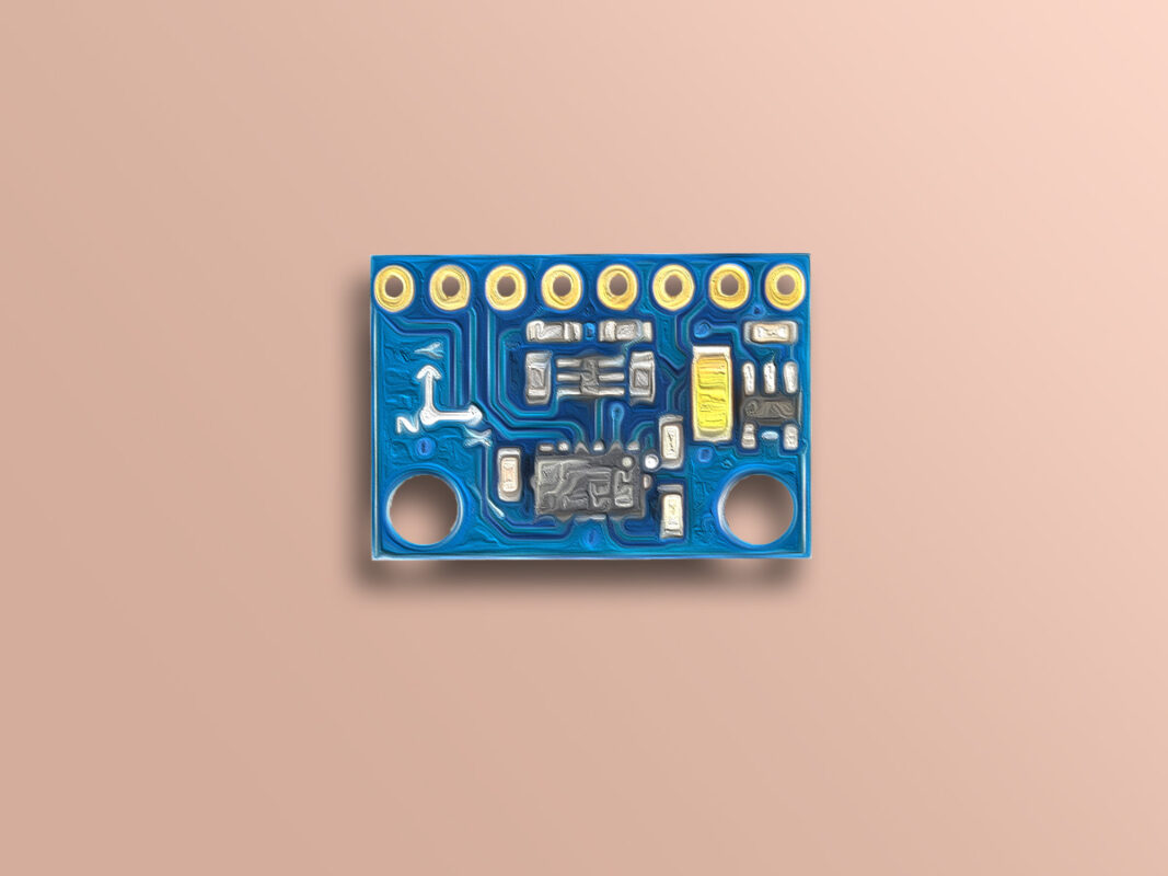
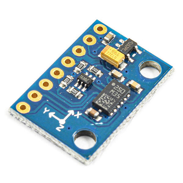
The GY-511 module uses the LSM303DLHC chip to detect and direct magnetic fields. The communication protocol of this module is I2C and you can connect it to different processors including Arduino boards using SCL and SDA pins.
You can download the LSM303DLHC chip datasheet here.
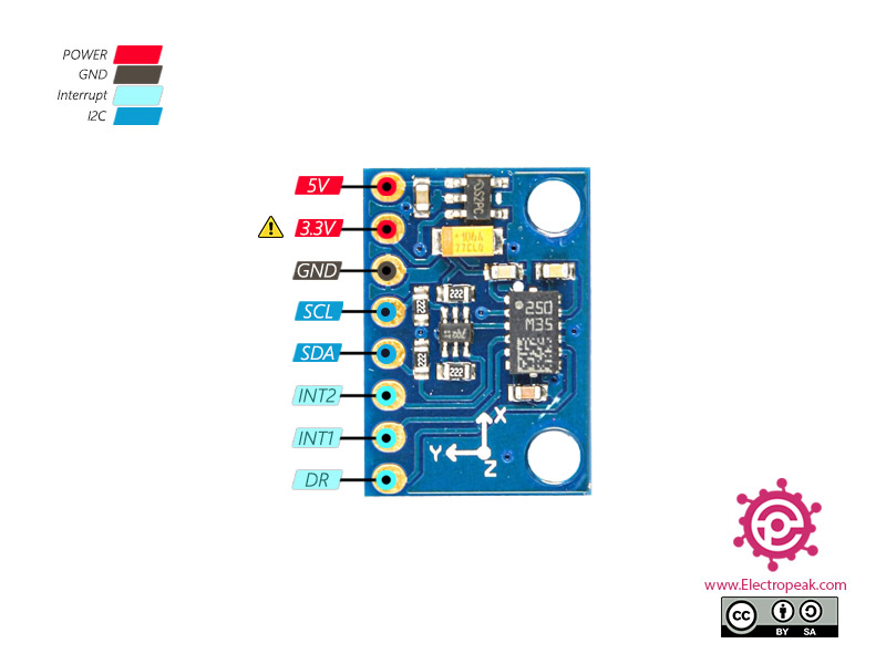
3V: There is a 5 to 3.3 volt regulator on the module. You can use this pin to power the rest of the circuit, which requires 3.3 volts. The maximum current that can be supplied by this pin is 100 mA.
GND: Ground
SCL: Clock Pin for I2C communication
SDA: Data pin for I2C communication
INT2: Interruption 2
INT1: Interruption 1
DRDY (DataReady): This pin is activated when new values are measured by the sensor and sent to the output.
You can see the pinout of this module in the image below.
Note
Module interrupts are used to detect free fall and motion detection.
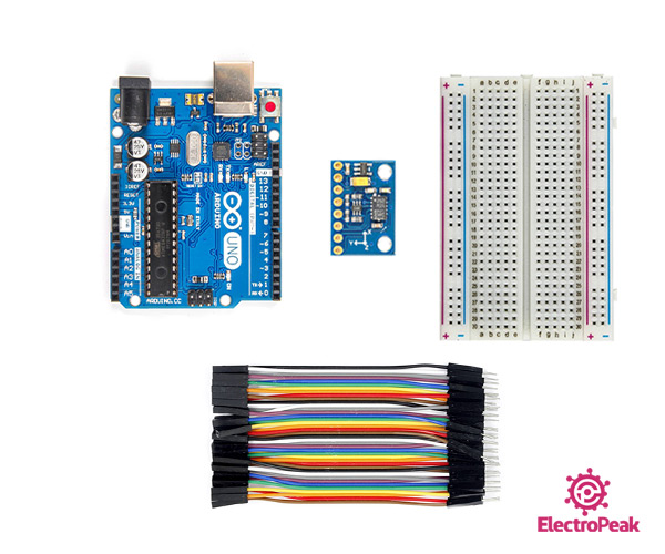
Required Materials
Hardware Components
Arduino UNO R3
×
1
GY-511 3-Axis Accelerometer
×
1
Breadboard
×
1
Male to Male jumper wire
×
1
Software Apps
Arduino IDE
Interfacing GY-511 Compass with Arduino
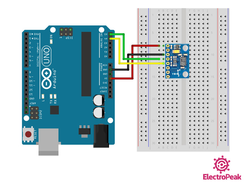
Step 1: Circuit
Connect the GY-511 module to Arduino according to the following diagram.
Step 2: Installing Library
Download and install the GY-511 module library here.
Note
If you need more help to install the library, visit here.
This library has a variety of examples for interfacing a compass module. You can also use these examples if needed.
Step 3: Code
After installing the library, upload the following code to your Arduino board. Then open the serial monitor to display the compass output.
You can also calibrate your sensor using library examples to make your measurements more accurate.
/*
GY-511 Compass
modified on 05 Sep 2020
by Mohammad Reza Akbari @ Electropeak