Introduction
Would you like to add audio capabilities to your projects? Well, you’ve come to the right place!
In this tutorial, we will learn how to interface the DY-SV17F mp3 player module with Arduino. Whether you are a beginner in electronics or a professional developer, this tutorial will help you easily get the DY-SV17F module up and running and play your audio files.
What You Will Learn
- How to establish UART communication with Arduino
- Introduction to the DY-SV17F mp3 player module
DY-SV17F MP3 Player Module – Features
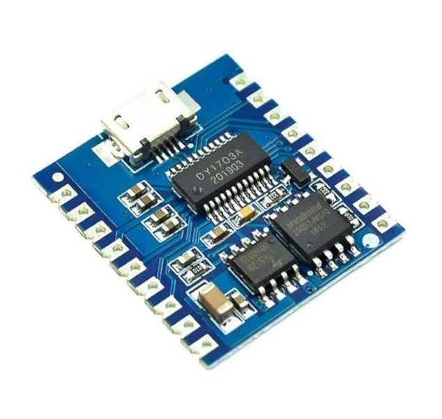
The DY-SV17F MP3 Player module comes with several attractive features that set it apart from other audio player modules.
Some of these features include a 5w amplified audio output, 4MB of built-in memory, and, above all, the ability to control it in three ways (serial communication, digital, and push buttons).
For more information, you can download the DY-SV17F MP3 player module datasheet from this link.
DY-SV17F Module – Pinout and Modes
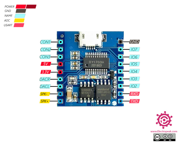
This module has 8 IO pins for addressing the audio file numbers and 3 CON pins for setting the operating mode.
Here is the pinout of the DY-SV17F module:
To set the operating modes, you must set these pins as follows:
UART Mode
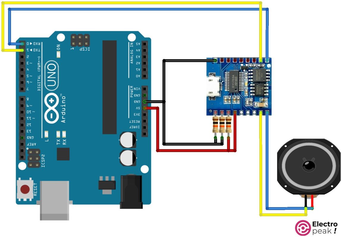
Connect CON1 to GND, CON2 to GND, and CON3 to 5v. In this mode, IO0 and IO1 pins act as TXD and RXD.
I/O Integrated 0 Mode
Connect CON1 to GND, CON2 to GND, and CON3 to GND. This mode supports 255 audio files. By setting the I/O pins, you can select and play a specific file. When you make the pins go HIGH, it will play the audio file to the end and then stop.
If another file is selected while playing, the new file will be played to the end.
If the I/O inputs are set to a file, after playing the audio file, it will start playing again from the beginning.
During the playback, CON3 acts as an output, going HIGH, and it goes LOW when the playback is stopped.
I/O Integrated 1 Mode
Connect CON1 to 5V, CON2 to GND, and CON3 to GND. This mode also supports 255 audio files. By setting the I/O pins, you can select and play a specific file. When you make the pins go HIGH, it will stop the playback.
If the I/O inputs are set to a file, after playing the audio file, it will start playing again from the beginning.
During the playback, CON3 acts as an output, going HIGH, and it goes LOW when the playback is stopped.
I/O Independent 0 Mode
Connect CON1 to GND, CON2 to 5V, and CON3 to GND. This mode supports 8 audio files. By going LOW on each of the I/Ox pins (x: pin number), the audio file with the same number will be played. When you make the pins go HIGH, it will play the audio file to the end and then stop.
If another file is selected while playing, the new file will be played to the end.
If the I/O inputs are set to a file, after playing the audio file, it will start playing again from the beginning.
During the playback, CON3 acts as an output, going HIGH, and it goes LOW when the playback is stopped.
I/O Independent 1 Mode
Connect CON1 to 5V, CON2 to 5V, and CON3 to GND. This mode also supports 8 audio files. By going LOW on each of the I/O pins (x: pin number), the audio file with the same number will be played. When you make the pins go HIGH, the playback will stop immediately.
If the I/O inputs are set to a file, after playing the audio file, it will start playing again from the beginning.
During the playback, CON3 acts as an output, going HIGH, and it goes LOW when the playback is stopped.
Standard MP3 Mode
Connect CON1 to 5V, CON2 to GND, and CON3 to 5v. In this mode, I/O0 to I/O4 pins act as NEXT/V+, PREV/V-, Play/Pause/MODE, EQ (Equalizer), and RPT (Repeat) keys, respectively.
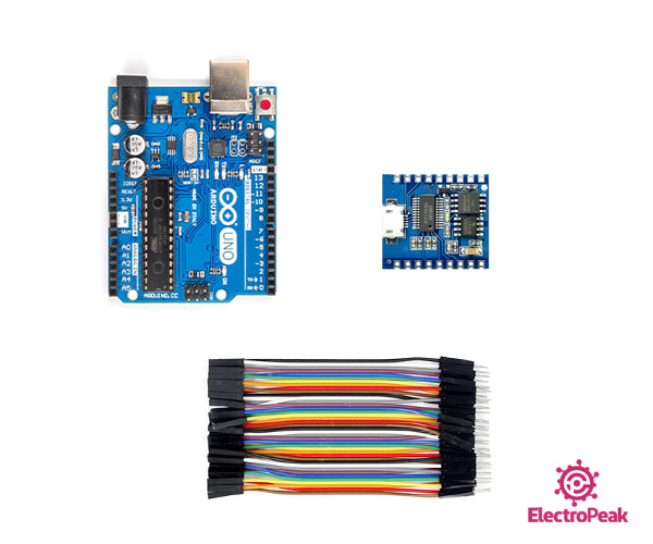
Required Materials
*: You can also use any other Arduino board that has a UART port.
Interfacing the DY-SV17F Module in UART Mode
Step 1: Wiring
Wire up the components as shown below.
Step 2: Code
The following code is to interface the Dy-SV17F module in serial mode.
First, download this library and install it in Arduino IDE.
Then upload the following code to your Arduino. The code includes comments to help you understand it better.
/*
modified on June 5, 2018
by SnijderC Chris from github.com/SnijderC/dyplayer/tree/master/examples/PlaySoundByNumber
<blockquote class="wp-embedded-content" data-secret="gbDSyleVCr"><a href="https://electropeak.com/learn/">Home</a></blockquote><iframe class="wp-embedded-content" sandbox="allow-scripts" security="restricted" style="position: absolute; clip: rect(1px, 1px, 1px, 1px);" title="“Home” — Electropeak" src="https://electropeak.com/learn/embed/#?secret=IMPV3iiZe7#?secret=gbDSyleVCr" data-secret="gbDSyleVCr" width="600" height="338" frameborder="0" marginwidth="0" marginheight="0" scrolling="no"></iframe>
*/
#include <Arduino.h>
#include "DYPlayerArduino.h"
// Initialise the player, it defaults to using Serial.
DY::Player player;
void setup() {
player.begin(); //initialize the module
player.setVolume(30); // Set Volume to 100%
}
void loop() {
player.playSpecified(1); //Play specified file
delay(5000); //wait for 5 second
}
Interfacing the DY-SV17F Module in I/O Integrated 0/1 Mode
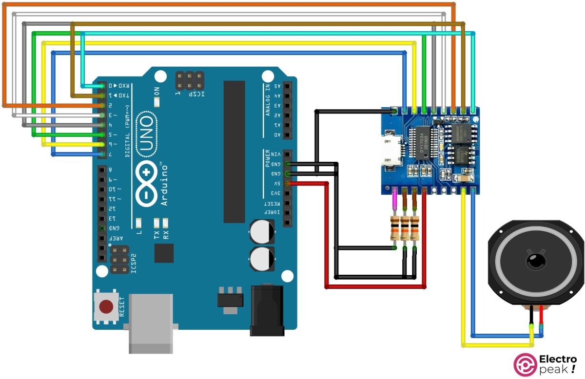
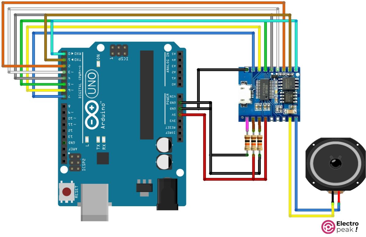
Step 1: Wiring
Wire up the components as shown below. This circuit is for I/O Integrated 0 mode. To switch to I/O Integrated 1 mode, disconnect the resistor leg—attached to the pink wire—from GND and connect it to 5v.
Step 2: Code
Upload the following code to your Arduino. The code includes comments to help you understand it better.
					int TrackNo = 0x01;
unsigned long previousMillis = 0;
const long interval = 1000;

void setup() {
  DDRC = 0xFF; //Setup Pins 0-7 as output
  pinMode(8, INPUT_PULLUP); //Next track
  pinMode(9, INPUT_PULLUP); //Previous track
  PORTC = TrackNo; //Select and play track 1
}

// the loop function runs over and over again forever
void loop() {
  unsigned long currentMillis = millis();
  if (currentMillis - previousMillis >= interval)//Play for 10 seconds
  {
    if (TrackNo = 255)
      TrackNo = 0;
    TrackNo = TrackNo + 1;  //change track (increase track number)
    PORTC = TrackNo; //Select and play track with number 1 to 255
  }
  if(digitalRead(8) == LOW)
  {
    if (TrackNo = 255)
      TrackNo = 0;
    TrackNo = TrackNo + 1;
    PORTC = TrackNo; //Select and play track with number 1 to 255
    delay(10);
  }
  if(digitalRead(9) == LOW)
  {
    if (TrackNo = 0)
      TrackNo = 256;
    TrackNo = TrackNo - 1;
    PORTC = TrackNo; //Select and play track with number 1 to 255
    delay(10);
  }
}
This code plays the files numbered 1 to 255 in sequence for 10 seconds. During the playback, if pins 8 or 9 are connected to GND by a switch, the audio file number being played will be increased or decreased by 1.
Interfacing the DY-SV17F Module in I/O Independent 0/1 Mode
Step 1: Wiring
Wire up the components as shown below. This circuit is for I/O Independent 0 mode. To switch to I/O Independent 1 mode, disconnect the resistor leg—attached to the pink wire—from GND and connect it to 5v.
Step 2: Code
Upload the following code to your Arduino. The code includes comments to help you understand it better.
					int Number = 0;
int TrackNo = 0x01;
unsigned long previousMillis = 0;
const long interval = 10000;

void setup() {
  DDRC = 0xFF; //Setup Pins 0-7 as output
  pinMode(8, INPUT_PULLUP); //Next track
  pinMode(9, INPUT_PULLUP); //Previous track
  PORTC = TrackNo; //Select and play track 1
}

// the loop function runs over and over again forever
void loop() {
  unsigned long currentMillis = millis();
  if (currentMillis - previousMillis >= interval)//Play for 10 seconds
  {
    if (Number = 7)
      Number = 0;
    else
      Number = Number + 1;  //change track (increase track number)
      TrackNo = 0xFF - 2 ^ Number;
    PORTC = TrackNo; //Select and play track with number 1 to 8
  }
  if (digitalRead(8) == LOW)
  {
    if (Number = 7)
      Number = 0;
    else
      Number = Number + 1;
    TrackNo = 0xFF - 2 ^ Number;
    PORTC = TrackNo; //Select and play track with number 1 to 8
    delay(10);
  }
  if (digitalRead(9) == LOW)
  {
    if (Number = 0)
      Number = 8;
    Number = Number - 1;
    TrackNo = 0xFF - 2 ^ Number;
    PORTC = TrackNo; //Select and play track with number 1 to 8
    delay(10);
  }
}
This code plays the files numbered 1 to 255 in sequence for 10 seconds. During the playback, if pins 8 or 9 of the Arduino board are connected to GND by a switch, the audio file number being played will be increased or decreased by 1.
Interfacing the DY-SV17F Module in I/O Independent 0/1 Mode with Push Buttons
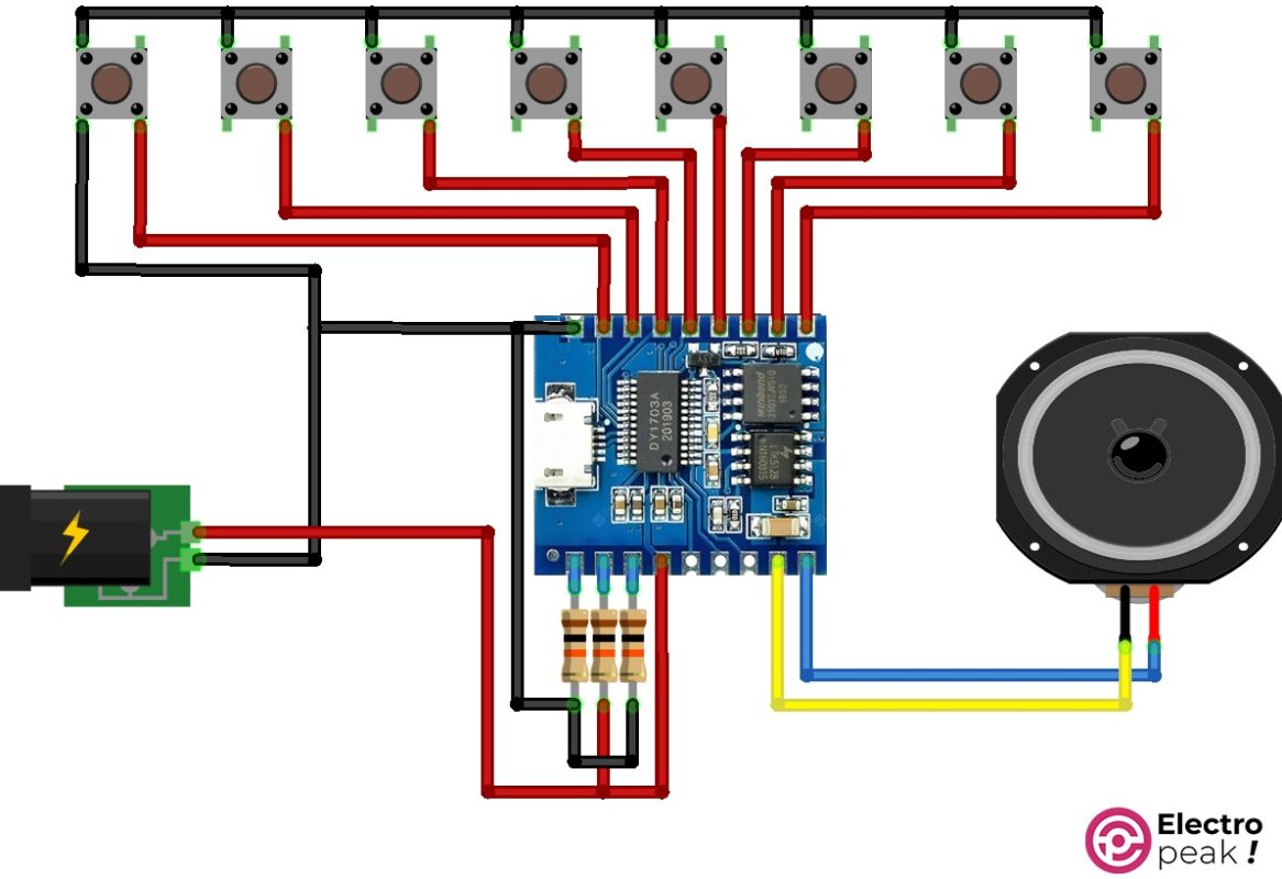
Wire up the components according to the image below. The circuit is for I/O Independent 0 mode.
By pushing each button, the audio files from 00001.mp3 to 00008.mp3 will be played
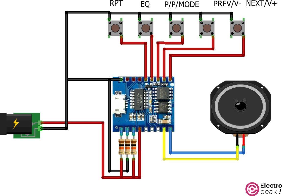
Interfacing the DY-SV17F Module in Standard MP3 Mod
Wire up the components according to the image below.
The function of each push button—connected to the module—is written next to it. With this wiring, you can have an mp3 player.
What’s Next?
In this tutorial, you learned about different methods of interfacing the DY-SV17F mp3 player module. As mentioned, you can run this module with just one button or use a microcontroller for more professional projects. Therefore, the DY-SV17F mp3 player module has many uses including playing music in elevators, musical dolls and toys, talking robots, etc.

Comments (17)
tried the example sketch it worked great, but how would i go calling 3 different sounds
Hi.
You can plug in your module to a computer via a USB to microUSB cable and store the sound files you want on it. You can store up to 255 files on this module, and you should name them 00001.mp3, 00002.mp3, 00003.mp3, …, 00255.mp3. Then, you can play your desired sound file by this command “player.playSpecified(file_name);” just like line 18 of the code in this tutorial.
hi, DY-SV17F powers up when connected via USB to PC. However, flash drive is not detected. I cannot upload any files. Any idea what would cause this?
Well, it can be due to many reasons. First, try another cable and USB PORT. Some cables just don’t work properly. If it still didn’t work, there might be something wrong with the DY-SV17F module itself.
Hello, Connecting CON3 pin directly connecting to 5V caused me some problems. I suggest putting 10k ohm res in between or directly connecting to 3.3v out of the DY-SV17F module.
Hi.
You are correct. Thanks for sharing your experience.
I can see the sound is playing at the DAC outputs, but the speaker outputs don’t work. I notice the SD pin on the amplifier pin 1 is HIGH, which I think means shutdown, but I haven’t been able to find how the module drives this pin…. cant find any schematic for the module itself… This problem sound familiar to anyone?
Hi.
which type of speaker did you use?
how did you know sound is playing?
Thanks a lot for the usefull information.
I hope to use this module with Raspberry Pi.
1. Are there any libraries for RPi?
2. Is there any way to interface with RPi only using USB port,
without connection to RX/TX?
Thanks in advance.
Hello Eagle,
The USB port is only for file uploads. Once you’ve uploaded your file to the module, you should disconnect the USB cable to activate the TTL port.
If you’re using a Raspberry Pi, you can use the AUX output with an amplifier to play sound directly
Hi Damirchi,
Thank you for your comments.
I hope to use the separate mp3 module because rpi aux sound generates the noise.
To avoid the noise, I want to connect this module to rpi usb, and gpio (sw serial),
mount and copy mp3 file onto sound module, and unmount it.
After that, send the play command to it by using sw serial.
Any comments for rpi library?
If the DY-SV17F is rated as ” 5W power amplifier access directly to 4-8Ohm horn.” How do you supply that amount of power to it? Arduino can not supply that amount of power? That is I*I*5 = 5 watts = 1 ampere.
Hi Harry,
You are correct that you need 1A to achieve 5W of power. If your speaker can handle 5W, you will need an external power source to supply that 1A. Typically, using a low-power speaker (1 to 2W) allows you to power it directly with Arduino.
Hi, I’d like to leave a comment: Usually to establish a serial communication it needs to connect TX on one side to RX on the other side and vice versa. The strange thing in my case is that connecting the MP3 to my ESP32-mini the correct way did not work. I connected TX–TX(pin21on ESP32) and RX–RX(pin 20 on ESP32) and it worked. What´s that about ???
Hello,
If you check the schematic of this module, you’ll notice that the TX pin marking on the PCB is internally connected to the RX pin of the ESP32. As a result, to make the module work properly, you need to connect it in **TX-to-TX** and **RX-to-RX** mode. This is because the connections inside the development board are reversed.
I can not upload the code to the arduino uno when the Tx pin is connected
Hi Julian,
That’s correct. The TX and RX pins on the Arduino are also used for programming. When you want to upload code to the Arduino, you need to disconnect any module connected to these two pins. After programming, you can reconnect them.