You can download the datasheet of this module here.

You can download the datasheet of this module here.

Comments (8)
1. How to connect to Nema 17 to DRV8833 ?
2. What is stepping sequence ?
Hi Peter,
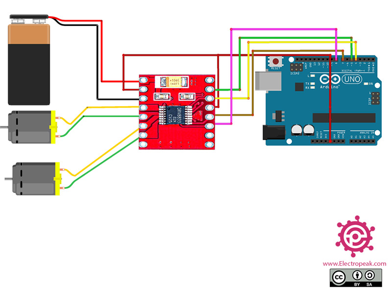
to connect Nema17 to DRV8833, u should use this wiring.
And this one for code
#include
// change this to the number of steps on your motor
#define STEPS 200
// create an instance of the stepper class, specifying
// the number of steps of the motor and the pins it's
// attached to
Stepper stepper(STEPS, 4, 5, 6, 7);
void setup()
{
Serial.begin(9600);
Serial.println("Stepper test!");
// set the speed of the motor to 30 RPMs
stepper.setSpeed(60);
}
void loop()
{
Serial.println("Forward");
stepper.step(STEPS);
Serial.println("Backward");
stepper.step(-STEPS);
}
1. Is it possible to add an rf module (nrf240lL01) to make an RC?
“Hi Arhi,
Certainly, you can!
NRF24 provides wireless communication, enabling you to transmit RC data.
If you’re interested in using your phone as a remote control for your RC, consider the ESP32.(no need use an Arduino) and handle every thing.
How do you connect the same DRV8833 modul with N20 motors and Uno R3 arduino to make a line follower robot? any way since i tried the same but it doesnt seem to work
Hello,
DRV8833 serves as a motor driver, while N20 is a compact motor. To create a line follower, incorporate IR sensors to detect the line, utilize an Arduino to interpret this data, and send commands to the motor driver to control movement.
you can read this links too. link1 link2
Hi,
i am a rookie so i do not know that much about robotics, but is it possible to connect multiple drivers to one arudino uno r4 board?
Hello,
Yes, it is possible to connect multiple motor drivers to a single Arduino. However, the number of motors you can connect depends on the available digital pins on your Arduino. Additionally, if you intend to control the speed of the motors, you will need to connect them to PWM (Pulse Width Modulation) pins, and the number of PWM pins will also limit how many motors you can control simultaneously.