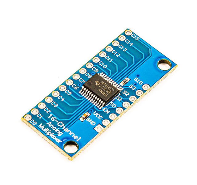
If you’re looking to interface the CD74HC4067 16-Channel Multiplexer with Arduino, you’ve come to the right place. In this guide, we’ll walk you through the features of the CD74HC4067 module, provide a pinout diagram, and explain the steps to connect it to an Arduino. By following this guide, you’ll be able to effectively use the CD74HC4067 multiplexer in your analog input projects.
CD74HC4067 16-Channel Multiplexer Features
The CD74HC4067 16-Channel analog-digital multiplexer module can be used when there are many analog inputs in a circuit. In this case, one of these inputs needs to be selected and processed each time. This multiplexer can be used to select from 16 analog inputs. There are four S0-3 pins, which by giving appropriate values, one of the analog inputs is set as the output in the SIG pin.
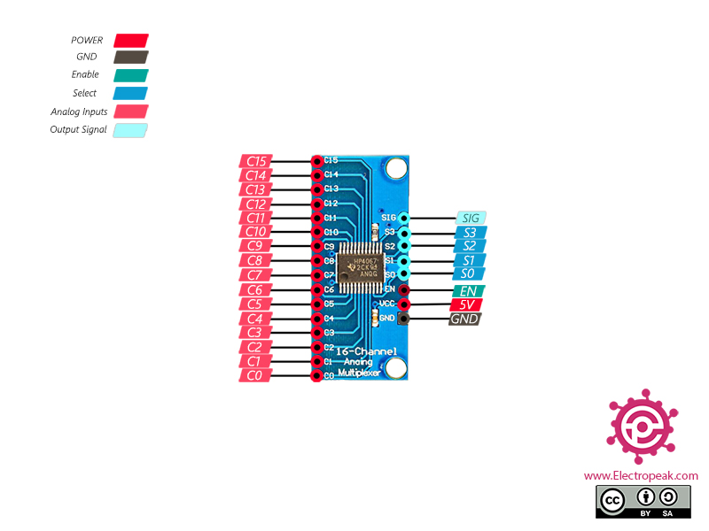
CD74HC4067 16-Channel Multiplexer Pinout
This module has 24 pins:
- VCC: Module power supply – 5V
- GND: Ground
- EN: Enable pin (Active Low)
- S0-3: Selecting one of 16 analog input pins as the final output signal
- C0-15: Analog inputs
- SIG: Output signal
You can see the pinout of this module in the image below.
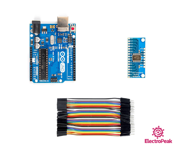
Required Materials
Hardware Components
Software Apps
Interfacing CD74HC4067 16-Channel Multiplexer with Arduino
Now, let’s get into the step-by-step process of interfacing the CD74HC4067 multiplexer with an Arduino.
Step 1: Circuit
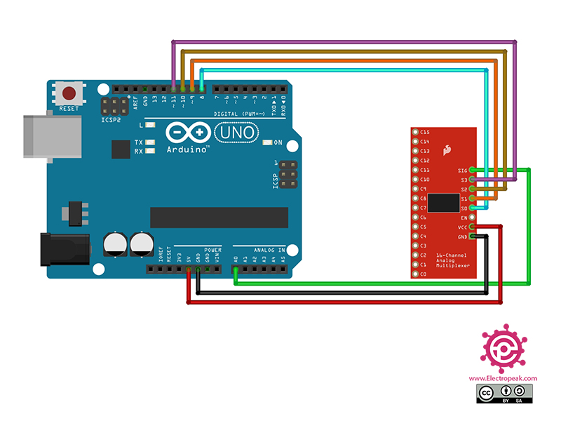
The following circuit shows how you should connect Arduino to CD74HC4067 module. Connect wires accordingly.
Then you can connect the desired analog inputs to pins C0-15.
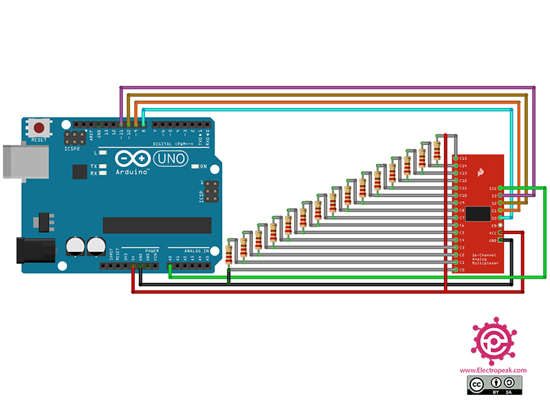
To test the performance of the circuit and code, you can use a voltage divider according to the following circuit.
Step 2: Code
connect the voltage divider circuit as shown above. Upload the following code to Arduino. After uploading the code, open the Serial Monitor.
 /*
Modified on Nov 28, 2020
Modified by MehranMaleki from Arduino Examples
Home
*/


//Mux control pins
int s0 = 8;
int s1 = 9;
int s2 = 10;
int s3 = 11;

//Mux in "SIG" pin
int SIG_pin = 0;


void setup(){
  pinMode(s0, OUTPUT);
  pinMode(s1, OUTPUT);
  pinMode(s2, OUTPUT);
  pinMode(s3, OUTPUT);

  digitalWrite(s0, LOW);
  digitalWrite(s1, LOW);
  digitalWrite(s2, LOW);
  digitalWrite(s3, LOW);

  Serial.begin(9600);
}


void loop(){

  //Loop through and read all 16 values
  for(int i = 0; i < 16; i ++){
    Serial.print("Value at channel ");
    Serial.print(i);
    Serial.print("is : ");
    Serial.println(readMux(i));
    delay(1000);
  }

}


float readMux(int channel){
  int controlPin[] = {s0, s1, s2, s3};

  int muxChannel[16][4]={
    {0,0,0,0}, //channel 0
    {1,0,0,0}, //channel 1
    {0,1,0,0}, //channel 2
    {1,1,0,0}, //channel 3
    {0,0,1,0}, //channel 4
    {1,0,1,0}, //channel 5
    {0,1,1,0}, //channel 6
    {1,1,1,0}, //channel 7
    {0,0,0,1}, //channel 8
    {1,0,0,1}, //channel 9
    {0,1,0,1}, //channel 10
    {1,1,0,1}, //channel 11
    {0,0,1,1}, //channel 12
    {1,0,1,1}, //channel 13
    {0,1,1,1}, //channel 14
    {1,1,1,1}  //channel 15
  };

  //loop through the 4 sig
  for(int i = 0; i < 4; i ++){
    digitalWrite(controlPin[i], muxChannel[channel][i]);
  }

  //read the value at the SIG pin
  int val = analogRead(SIG_pin);

  //return the value
  float voltage = (val * 5.0) / 1024.0;
  return voltage;
}
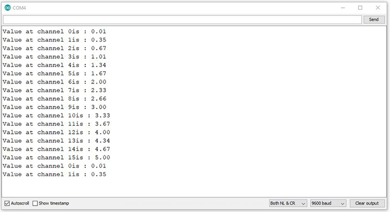
In the above code, by giving the appropriate values to pins S0-3 per second, we select pins C0-15, respectively, and the SIG pin voltage which should be equal to selected pin, appears on Serial Monitor.
The output is as follows.

Comments (14)
For code, I would suggest using the light_CD74HC4067 library.
The code that you have shown in this tutorial is quite memory-consuming.
light_CD74HC4067 will save much more memory and is easy to use. This library can be downloaded through Arduino IDE.
If I need to make it 32 (basically two of these ICs), does that mean 10 pins from the Arduino? I was trying to use the ATMega2560 and add 32 more pins to it
Hi BV,
To use 32 ADC pins, u need 2 ADC pins from your Arduino, like A0 and A1, and 8 digital pins for the Selector pin of CD74HC4067.
You could probably use a NO/NC relay and connect to the _EN pin on each of the two multiplexer chips or two digital outputs to select each chip and the same address pins for both chips or there are probably chips that you can address using SPI or I2C
Hello Adrian,
That’s correct! You can utilize the EN pin (there’s no need for a relay; simply connect both EN pins to the Arduino or use a transistor to invert the output).
However, it’s important to note that this chip doesn’t support SPI or I2C and operates solely with Parallel communication.
In such conditions, you can establish Parallel wiring between these two ICs. (only 4 line of data)
Mohammad – I have a need for at least 48 if not 54 I/O channels. 24 input (toggle switch) and 24 output to control relay boards. What is the best way to do this? I know multiplexers need to be involved but the largest multiplexer I’ve seen out there is a 16 channel. Does a 24 channel or a 32 channel multiplexer exist?
Thanks
Hello,
For the input values, you need to use two CD74HC4067 modules. Connect all the configuration pins together, except the SIG pins — those should be connected to two different Arduino pins. Then, use a loop to scan both SIG pins and store the 32 toggle pin states in an array.
For the output pins that control the relay module, the best option is to use a 74HC595 shift register. You can read more about this in the related article.
How will it work without pulling the EN pin to LOW (Ground) ? The EN pin is active LOW
Hello,
The Enable pin operates on an Active-LOW logic.
Setting the EN pin to HIGH disables the multiplexer output.
I’m really sad that the makersphere is getting filled with this AI garbage.
And then I have to “prove” I’m not a robot to post this.
Hi, I have a question? Can I connect the four wires of the mux on analog pins too? You see, I am stuck with an Arduino nano and I have all other digital pins occupied by other devices. It is a different project than this
Hello Ahmad,
Yes, you can use the analog pins of the Arduino Nano as digital pins, except for A6 and A7.
Good job thank you. What,s value of the resistor you used
Hello Daniel,
The resistor value is just an example—you can use any resistor value as long as all of them are the same.
The main focus of this article is to demonstrate how to read 16 analog sensors.