
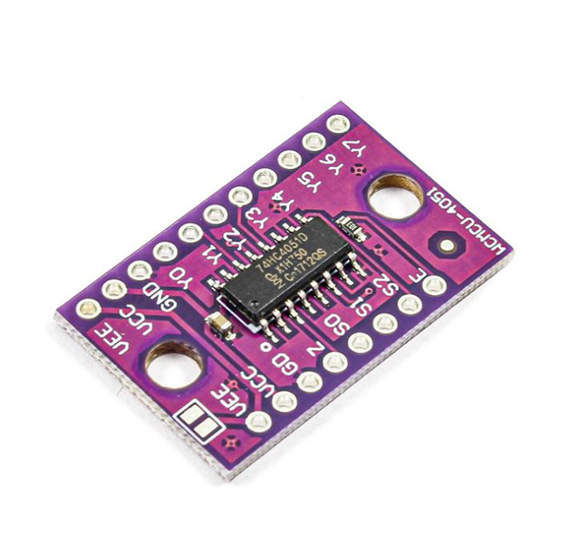
74HC4051 8-Channel Analog Multiplexer Features
The 74HC4051 8-Channel analog multiplexer module can be used when there are many analog inputs in a circuit. In this case, one of these inputs needs to be selected and processed each time. This multiplexer can be used to select from 8 analog inputs. There are three S0-2 pins, which by giving appropriate values, one of the analog inputs is set as the output on the Z pin.
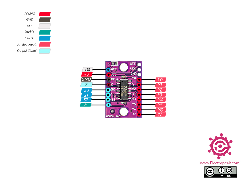
74HC4051 8-Channel Multiplexer Pinout
This module has 19 pins:
Left Side:
- VEE: Negative power supply (Can be left unconnected)
- VCC: Module power supply – 5V
- GND: Ground
- Z: Output signal
- S0-2: Selecting one of the 8 analog input pins as the final output signal
- E: Enable pin (Active Low)
Right Side:
- VEE: Negative power supply (Can be left unconnected)
- VCC: Module power supply – 5V
- GND: Ground
- Y0-7: Analog inputs
Note
The VEE, VCC, and GND pins are connected to each other on both sides of the module and no need to supply power to both side.
You can see the pinout of this module in the image below.
Required Materials
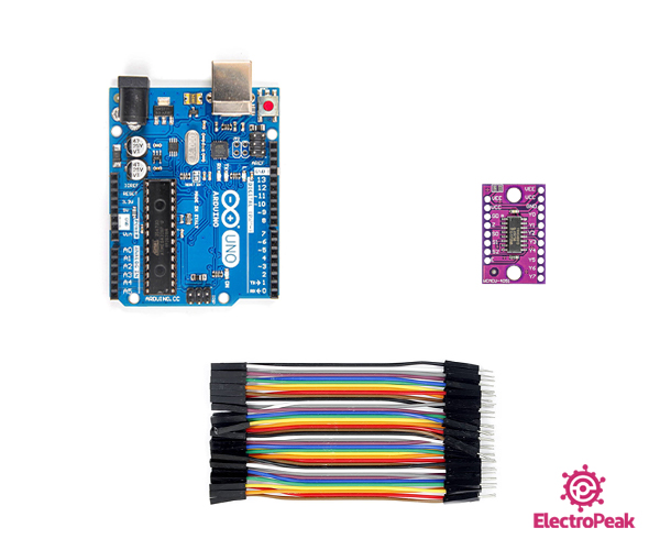
Hardware Components
Software Apps
Interfacing 74HC4051 8-Channel Multiplexer with Arduino
Step 1: Circuit
The following circuit shows how you should connect Arduino to 74HC4051 module. Connect wires accordingly.
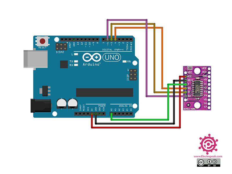
Then you need to connect the desired analog inputs to pins Y0-7.
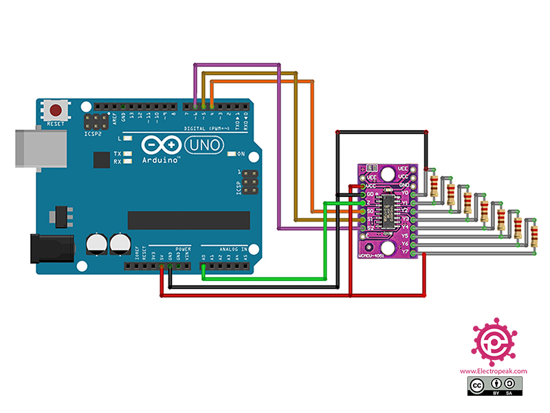
To test the function of circuit and code, you can use a voltage divider according to the following circuit.
Step 2: Code
Upload the following code to Arduino. After that open the Serial Monitor.
 /*
Modified on Dec 1, 2020
Modified by MehranMaleki from Arduino Examples
Home
*/


//Mux control pins
int s0 = 4;
int s1 = 5;
int s2 = 6;

//Mux in "Z" pin
int Z_pin = 0;


void setup(){
  pinMode(s0, OUTPUT);
  pinMode(s1, OUTPUT);
  pinMode(s2, OUTPUT);

  digitalWrite(s0, LOW);
  digitalWrite(s1, LOW);
  digitalWrite(s2, LOW);

  Serial.begin(9600);
}


void loop(){

  //Loop through and read all 8 values
  for(int i = 0; i < 8; i ++){
    Serial.print("Value at channel ");
    Serial.print(i);
    Serial.print("is : ");
    Serial.println(readMux(i));
    delay(1000);
  }

}


float readMux(int channel){
  int controlPin[] = {s0, s1, s2};

  int muxChannel[8][3]={
    {0,0,0}, //channel 0
    {1,0,0}, //channel 1
    {0,1,0}, //channel 2
    {1,1,0}, //channel 3
    {0,0,1}, //channel 4
    {1,0,1}, //channel 5
    {0,1,1}, //channel 6
    {1,1,1}, //channel 7
  };

  //loop through the 3 sig
  for(int i = 0; i < 3; i ++){
    digitalWrite(controlPin[i], muxChannel[channel][i]);
  }

  //read the value at the Z pin
  int val = analogRead(Z_pin);

  //return the value
  float voltage = (val * 5.0) / 1024.0;
  return voltage;
}
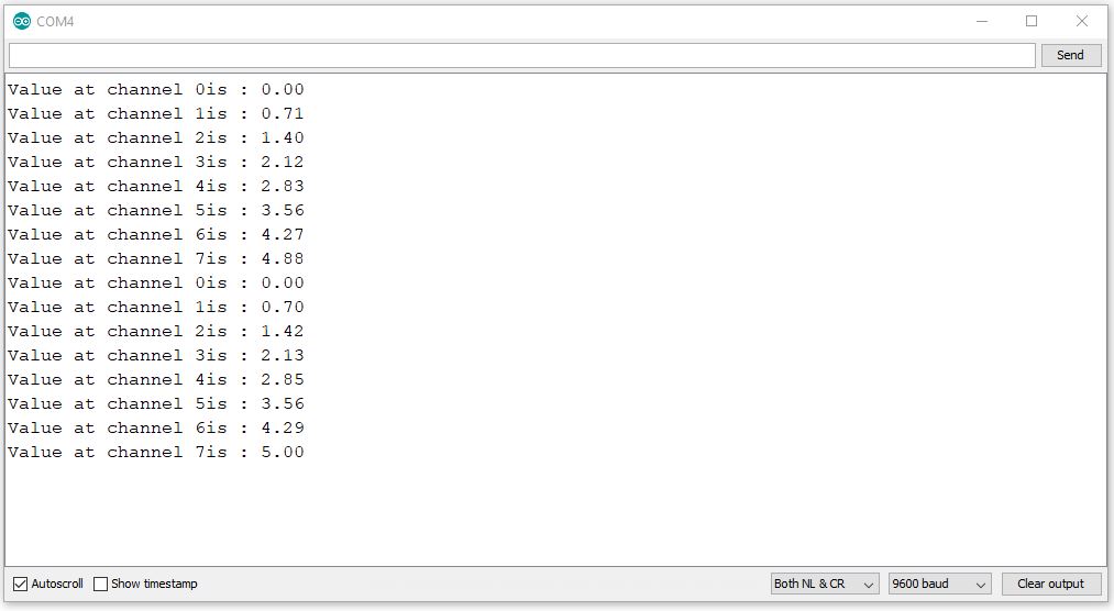
In the above code, by giving the appropriate values to pins S0-2 per second, we select pins Y0-7 respectively, and the Z pin voltage which should be equal to the selected pin, appears on Serial Monitor.
The output is as follows.

Comments (4)
I don’t know about this module, but when using the raw chip, VEE should be connected to GND for this usage. And 20uF between GND and VCC. The code also needs to add a delay after switching to allow the device to settle.
Hi,
thank you for providing details about your raw IC.
Upon examining this model, I noticed a capacitor for VCC and a jumper for VEE, which is connected to GND but can be disconnected to connect to a negative voltage.
Is it possible to use this multiplexer with just a 3.3V power supply?
Hi Paul,
According to the datasheet of the 74HC4051 (page 6), the minimum supply voltage is 4.5V.
If you can purchase the 74HCT4051 instead, it supports a minimum supply voltage of 2V,