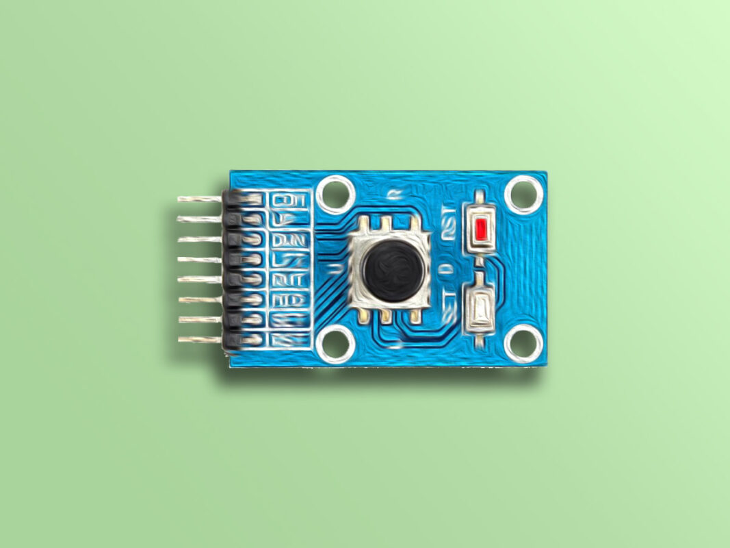
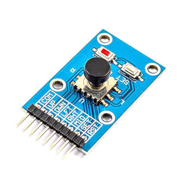
5 Direction Joystick Button Module Features
The 5 direction joystick button module is actually a combination of 5 pushbuttons that can be used in simple games. It is capable of connecting to a variety of microcontrollers. this module has 5 keys: Up, Down, Left, Right, Middle; And two additional keys: Set and Reset. This module works based on a common pin, COM. This means that by pressing each key, the related pin will connect to COM pin.
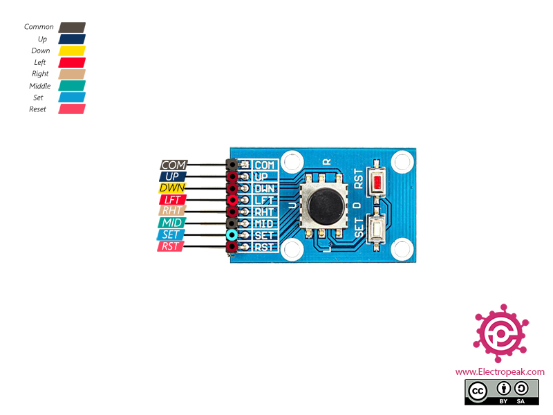
5 Direction Joystick Button Module Pinout
This Module has 8 pins:
- COM: Common pin
- UP: Up
- DWN: Down
- LFT: Left
- RHT: Right
- MID: Middle
- SET: Set pin
- RST: Reset pin
You can see the pinout of this module in the image below.
Required Material
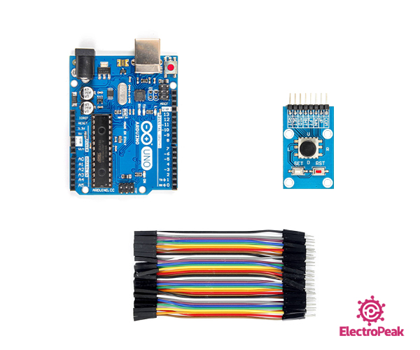
Hardware component
Software Apps
Interfacing 5 Direction Button Module with Arduino
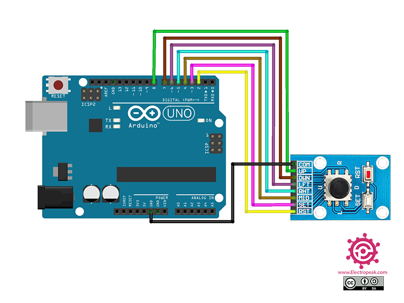
Step 1: Circuit
The following circuit show how you should connect Arduino to this module. Connect wires accordingly.
Step 1: Code
Upload the following code to your Arduino. After that open Serial Monitor.
  /*
  Made on Dec 12, 2020
  By MehranMaleki @ Electropeak
  Home
*/


const int buttonPin_RST = 2;     // the number of the reset button pin
const int buttonPin_SET = 3;     // the number of the set button pin
const int buttonPin_MID = 4;     // the number of the middle button pin
const int buttonPin_RHT = 5;     // the number of the right button pin
const int buttonPin_LFT = 6;     // the number of the left button pin
const int buttonPin_DWN = 7;     // the number of the down button pin
const int buttonPin_UP = 8;      // the number of the up button pin


void setup() {
  Serial.begin(9600);

  pinMode(buttonPin_RST, INPUT_PULLUP);
  pinMode(buttonPin_SET, INPUT_PULLUP);
  pinMode(buttonPin_MID, INPUT_PULLUP);
  pinMode(buttonPin_RHT, INPUT_PULLUP);
  pinMode(buttonPin_LFT, INPUT_PULLUP);
  pinMode(buttonPin_DWN, INPUT_PULLUP);
  pinMode(buttonPin_UP, INPUT_PULLUP);
}

void loop() {
  if(digitalRead(buttonPin_RST) == LOW) {
    delay(250);
    Serial.println("Reset Pin Is Pressed.");
    while(digitalRead(buttonPin_RST) == LOW);
  }

  if(digitalRead(buttonPin_SET) == LOW) {
    delay(250);
    Serial.println("Set Pin Is Pressed.");
    while(digitalRead(buttonPin_SET) == LOW);
  }

  if(digitalRead(buttonPin_MID) == LOW) {
    delay(250);
    Serial.println("Middle Pin Is Pressed.");
    while(digitalRead(buttonPin_MID) == LOW);
  }

  if(digitalRead(buttonPin_RHT) == LOW) {
    delay(250);
    Serial.println("Right Pin Is Pressed.");
    while(digitalRead(buttonPin_RHT) == LOW);
  }

  if(digitalRead(buttonPin_LFT) == LOW) {
    delay(250);
    Serial.println("Left Pin Is Pressed.");
    while(digitalRead(buttonPin_LFT) == LOW);
  }

  if(digitalRead(buttonPin_DWN) == LOW) {
    delay(250);
    Serial.println("Down Pin Is Pressed.");
    while(digitalRead(buttonPin_DWN) == LOW);
  }

  if(digitalRead(buttonPin_UP) == LOW) {
    delay(250);
    Serial.println("Up Pin Is Pressed.");
    while(digitalRead(buttonPin_UP) == LOW);
  }
}
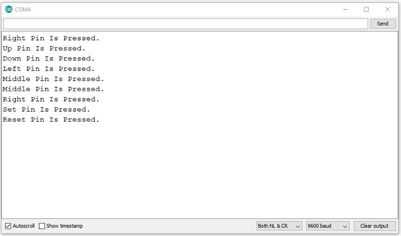
In the above code, each key is set as an input to one of the Arduino pins. By pressing each key, it will appear on the Serial Monitor.
The output is as follows.