Interfacing PWM Signal Generator Module, Stepper Motor Driver
Written by
Amir Mohammad Shojaei
PWM Signal Generator Module, Stepper Motor Driver Features
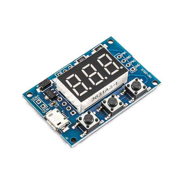
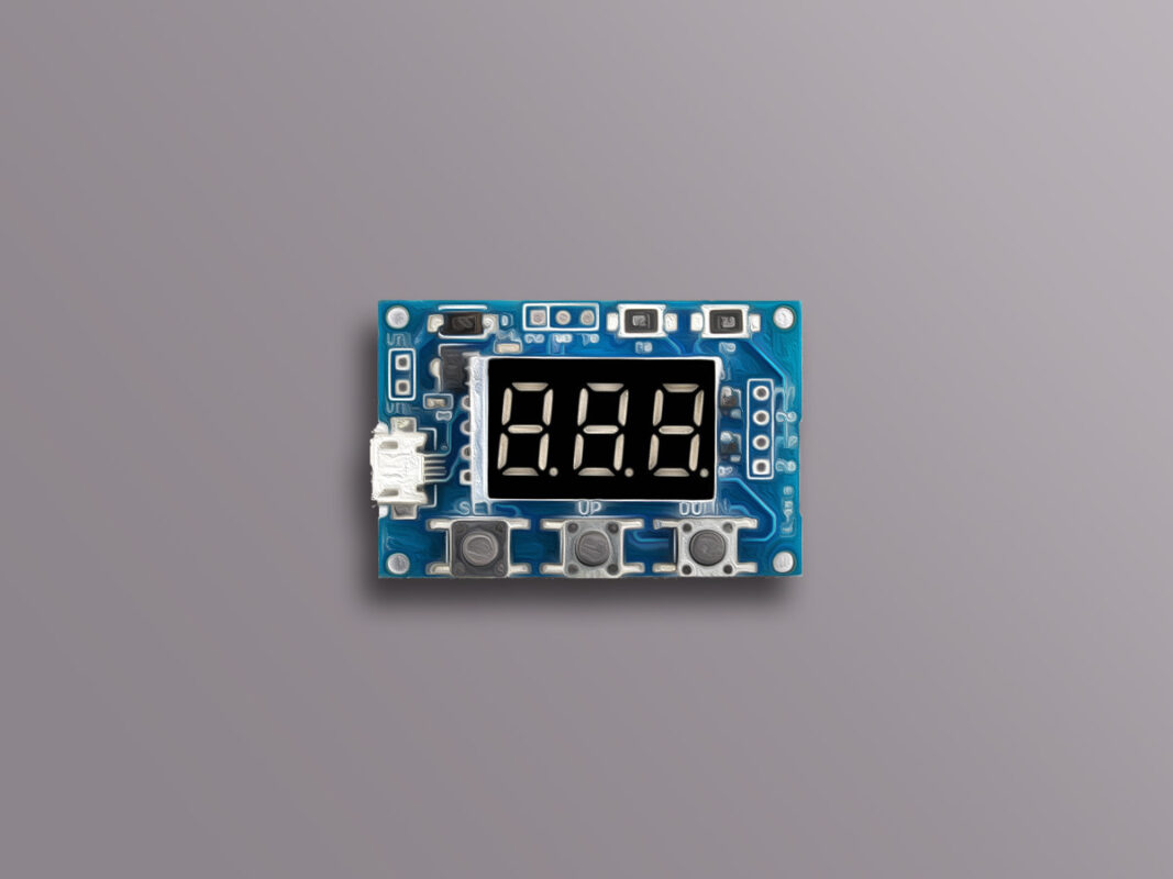
The signal generator module is used to generate a square pulse with adjustable frequency and duty cycle in 2 different channels. This module has 3 microswitches to adjust the pulses. It also has a micro USB input for powering the module. There are also two other pins for connecting the power supply. The two PWM outputs of this module are independent, and you can generate your desired pulses on them.
Features:
Operating voltage: 5 – 30V
Frequency range: 1Hz – 150KHz
Frequency Precision: 2%
Applications:
Generate square waves
Stepper motor driver
Generate adjustable pulses for MCU
Generate adjustable pulses for circuit controlling
How to Adjust PWM Signal Generator Module, Stepper Motor Driver
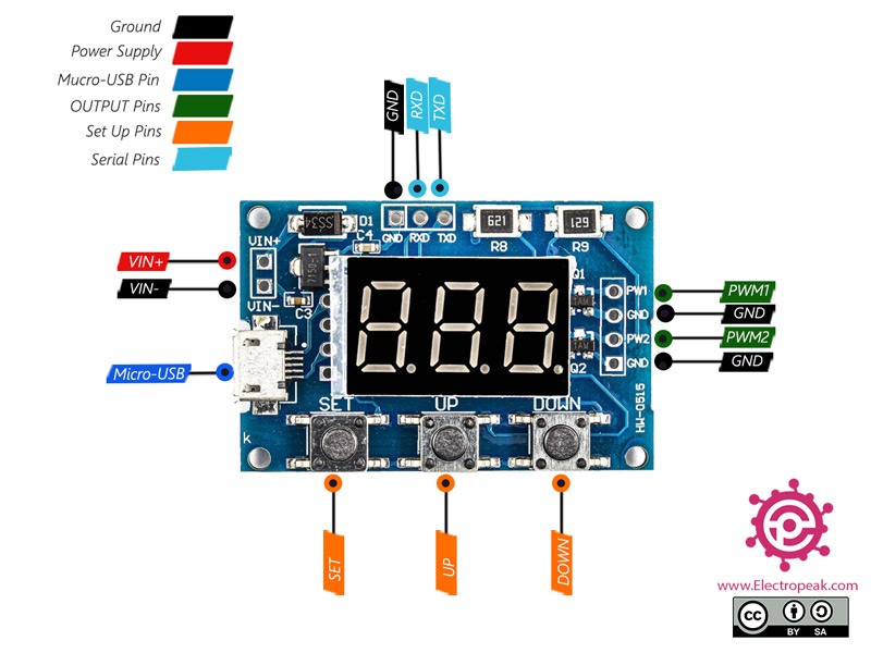
The output pulses are controlled entirely by three onboard microswitches. From left to right are: SET, UP and DOWN.
The Frequency and Duty Cycle of these two channels can be adjusted; Frequency from 1Hz to 150kHz and Duty Cycle from 0 to 100%:
Each time the SET button is pressed, the desired parameter will change.
These parameters are: the frequency of the first channel (FR1), Duty Cycle of the first channel (du1), the frequency of the second channel (FR2) and the Duty Cycle of the second channel (du2), respectively.
UP and DOWN switches are used to increase or decrease the value of these parameters.
You can change the frequency range by long pressing the SET button. These changes are as follows:
XXX: 1Hz to 999Hz
X: 1kHz to 99.9kHz
X.X: 1kHz to 150kHz
PWM Signal Generator Module, Stepper Motor Driver Pinout
This module has these pins:
VIN+: Positive pin for input voltage
VIN-: Negative pin for input voltage (electric ground)
GND: Electric ground
PWM1: PWM pulse channel 1
PWM2: PWM pulse channel 2
Micro-USB: Micro-USB input
SET: Setting switch
DOWN: Setting switch
UP: Setting switch
RXD: SerialReceive pin
TXD: Serial Transmit pin
You can see the pinout of this module in the image below.
Required Materials
Hardware Components
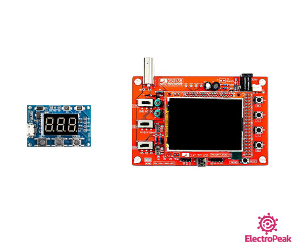
PWM Signal Generator Module
×
1
DSO138 Digital Oscilloscope
×
1
Software Apps
Arduino IDE
Note
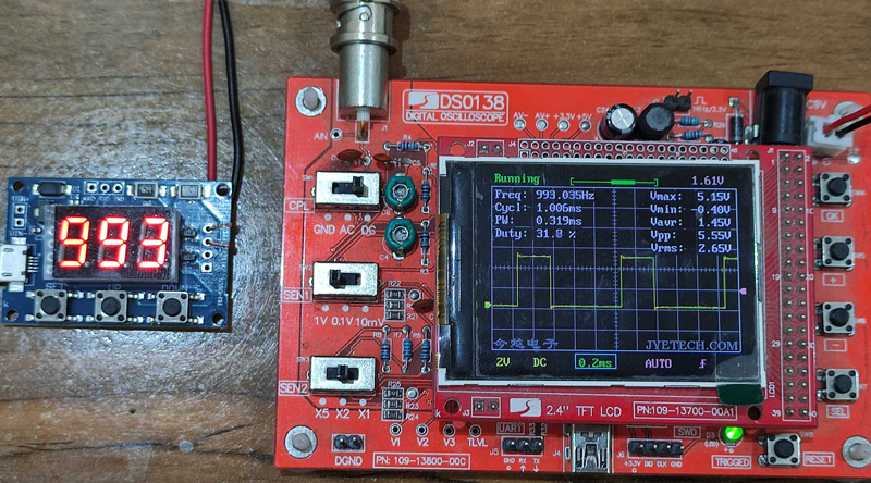
We use an oscilloscope to understand how this module works and to observe the pulses generated.
Interfacing PWM Signal Generator Module, Stepper Motor Driver
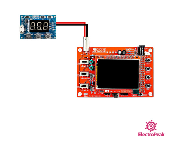
Step 1: Circuit
Power the signal generator module through micro USB port or another independent source. Then connect the module to the oscilloscope accordingly.
Note
Make sure the power supply is 5 to 30V.
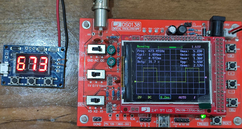
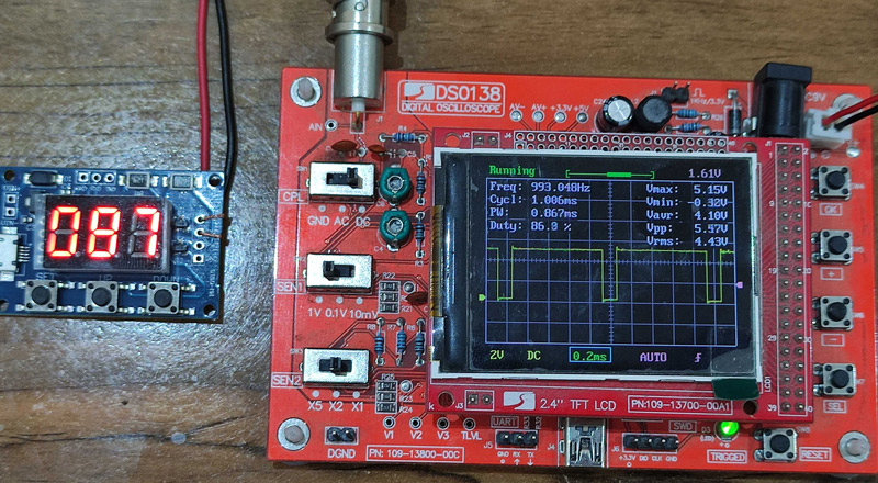
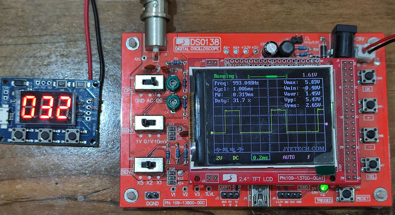
Step 2: Adjust and Observe the Pulse
We change the frequency and duty cycle of the first channel and observe the results on the oscilloscope:
Change the Frequency:
We reduced the frequency from 993 to 673. These changes can be seen in the oscilloscope:
Change the Duty Cycle:
In this part, we decreased the duty cycle from 87% to 32%. It can be seen that the pulse width decreases: