Product added to cart

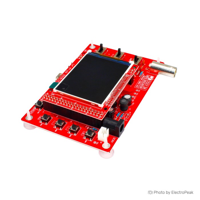
DSO138 Digital Oscilloscope With TFT 2.4" Display
$16.2500
In stock
SKU
TLS-10-002
Volume discounts:
- +25 4 % $15.6400
- +50 6 % $15.3300
- +100 8 % $15.0300
- +300 9 % $14.7200
- +500 11 % $14.4200
Ships in 2-3 business days, then:
Free delivery in10-15 days by YunExpress on orders over $35.
Free delivery in5-7 days by DHL on orders over $200.
More shipping info

Shop with confidence Learn More

DSO138 digital oscilloscope is a popular DIY digital oscilloscope kit. It's a low-cost oscilloscope designed for electronics enthusiasts and hobbyists to build their own oscilloscope for personal use.
A digital storage oscilloscope (often abbreviated DSO) is an oscilloscope that stores and analyses the signal digitally. It is now the most common type of oscilloscope in use because of the advanced trigger, storage, display and measurement features that it typically provides.
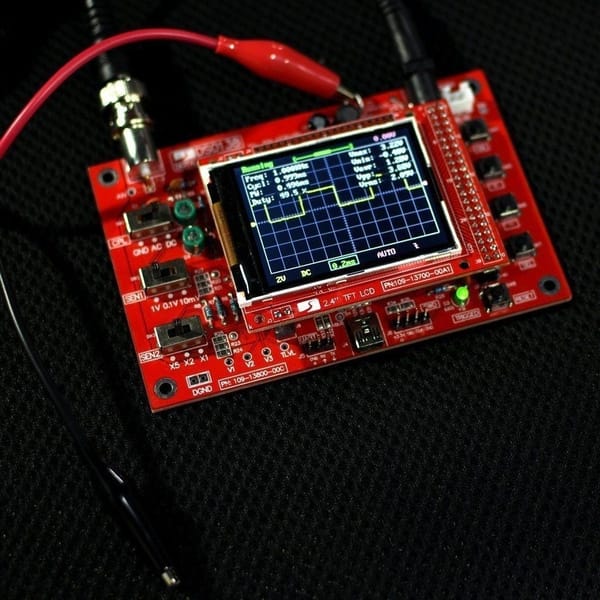
This kit includes everything you need to build your very own, fully functional, digital oscilloscope. Once you have got it up and running, the oscilloscope features up to 5M samples/second, 8-bit resolution, up to 50Vpp max input voltage, and more.
This kit includes a semi-populated PCB, with all of the surface mount components already soldered on for you. The components left for you to solder are all through-hole. This is on the higher end of difficulty as far as through-hole kits go.
DSO138 Digital Oscilloscope Features:
- This kit uses ARM Cortex-M3 processor, and includes a 2.4-inch color TFT display screen.
- With automatic, regular and one-shot modes, easy to capture the moment waveform
- Can be secondary developed to millivolt meter, data loggers
- Adjustable vertical displacement, and with instructions
- Available rising or falling edge trigger
- Observable previous trigger waveform (negative delay)
- Can freeze at any time waveform display (HOLD function)
- Comes 1Hz / 3.3V square wave test signal source
- Waveform storage: not lose the waveform after power off
- Short-circuit and open-circuit detection: can help the user find out the soldering error
Specifications of DSO138 Digital Oscilloscope:
- MCU: ARM Cortex-M3 (STM32F103C8 )
- Number of Channels: 1 Channel
- Analog Bandwidth: 0 ~ 200KHz
- Sensitivity: 10mV/Div ~ 5V/Div
- Input Impedance: 1M
- Accuracy: < 5%
- Resolution: 12 bit
- Maximum Measuring Voltage: 50Vpp (1: 1 probe), 400Vpp (10: 1 probe)
- Coupling: DC, AC, GND
- Max Real-time Sampling Rate: 1Msps
- Time-base: 10us/Div ~ 500s/Div
- Record Length: 1024
- Trigger Modes: Auto, Normal, Single
- Trigger Types: Rising/falling edge
- Trigger Position: 1/2 of buffer size fixed
- Display:4-inch color TFT LCD with 320 x 240 resolution
- Input Voltage: 8V ~ 12V
- Recommended Input Voltage: 9V
- Input Current: 120mA
- Size: 117mm x 76mm x 15mm
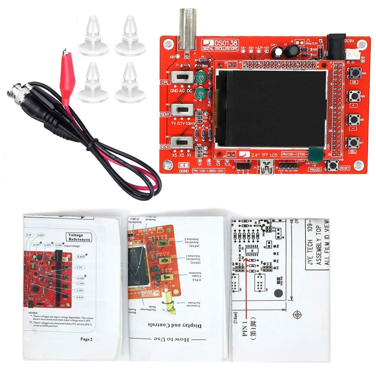
DSO138 Digital Oscilloscope Package content:
- 1 x DSO138 2.4³ TFT Digital Oscilloscope Kit
- 1 x Oscilloscope Cable

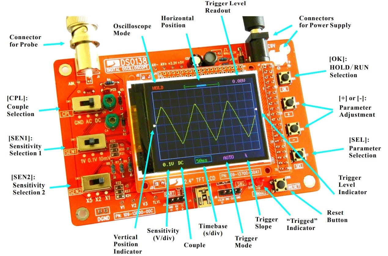
Connection ports of DSO138 Digital Oscilloscope
At the top of the DSO138 Digital Oscilloscope, there are a connector for probe and two different type power connector. At the bottom side, there are UART and ICSP header-pins-type connectors and a mini-USB connector for STM32 microcontroller firmware flashing.
Calibration and usage guide of DSO138 Digital Oscilloscope
Here are some helpful documents to get started with DSO138 Digital Oscilloscope:
- Users Manual [for 13803K/04K]
- Assembly Drawing
- Surface Mount Component Installation Guide
- SMD Parts List
- DSO138 Library
- How to Use the DSO138 Library
- Schematic of the LCD board
- How to Upgrade Firmware for DSO138
You can find more information on the DSO138 manufacturer's website.
Write Your Own Review

Please complete your information below to login.
Sign In
Create New Account