Contents

How to Use NE555 Pulse Generator Module

Introduction

 You’ve probably heard about the terms “pulse generating” or “PWM” before, or maybe even worked with them—for example, which Arduino pins can generate PWM pulses. They are widely used in Electronics for lots of things. Some of these applications include synchronizing digital systems, controlling engines and timers, as well as adjusting LED color and brightness. This concept also has its own place in all switching power supplies and other methods of controlling voltage and power.
Since the concept is super important, let’s take a quick look at it.

What is Pulse Width Modulation (PWM)?

PWM is a way to control and fine-tune the parameters of a square wave. The key parameters include frequency, duty cycle, and voltage amplitude.
Consider the figure below:

Period, Frequency, Duty Cycle, and Amplitude

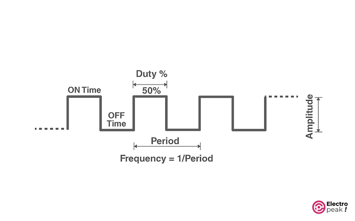
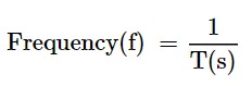
Period: The time it takes for a waveform to finish a cycle. It’s represented by “T” and measured in seconds (s).
Frequency: Inverse of the period. In other words: the number of cycles per second. It’s represented by “f” and measured in Hz (Hz=1/s).

Duty cycle: The ratio of on-time to the period. And it is usually given as a percentage.

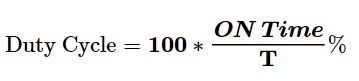
Example: Every two seconds, an electric voltage waveform goes on for 1.2 seconds and then off for 0.8 seconds; find the frequency and duty cycle.
Simple, isn’t it? Since the waveform repeats every 2 seconds, the period would be 2 s.
Frequency= 1/2= 0.5 Hz.
And Duty Cycle:

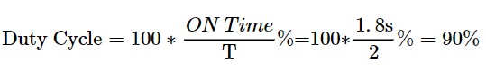
Here, We won’t dive into a full explanation of pulse width modulation and its applications. The Introduction we’ve given should suffice for our purposes. You can refer to the numerous articles about this topic if you need more information.
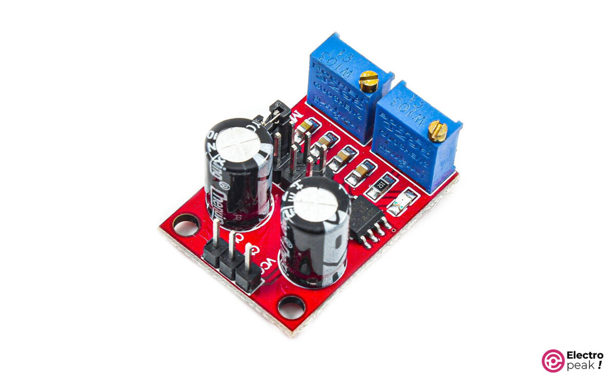
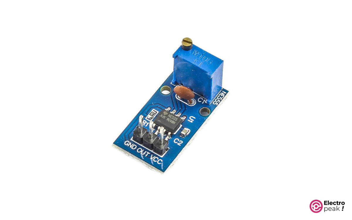
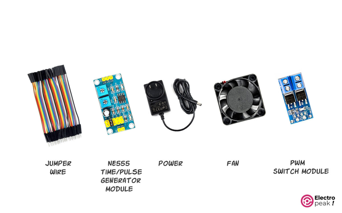
Now, let’s go through several models of square wave generators that have an NE555 IC.

NE555 Pulse Generator Module

Here are three types of NE555 pulse generator modules:

1Hz to 300kHz Pulse Generator

NE555 Pulse Generator Module (1Hz to 300KHz)

This pulse generator module uses an NE555 IC as its primary chip to generate square pulses ranging from 0.6 Hz to 300 kHz. And, it is equipped with five jumpers that enable users to select the desired frequency range for the generated pulse.

Additionally, the module features two potentiometers for precise adjustment of the pulse’s frequency and duty cycle.

This model has a great advantage—it simplifies the generation of pulses with desired specifications, all thanks to jumpers and potentiometers.
The model operates with an input voltage ranging from 5 to 12 volts, while the output voltage amplitude ranges from 4.2 to 11.4 volts depending on the input.

Specifications

• Pulse Frequency Range: 0.6 Hz to 200 kHz
• Duty Cycle Range: 0.4% to 0.99%
• Dimensions: 20 x 40 mm

1Hz to 200kHz Pulse Generator

NE555 Pulse Generator Module (1Hz to 200KHz)

The above module can generate square pulses from 0.6 Hz to 200 kHz. Other features of this module: 4 jumpers to determine the frequency range, and two potentiometers to adjust the frequency and duty cycle more precisely.
The model operates with an input voltage ranging from 5 to 12 volts, while the output voltage amplitude ranges between 4.2 and 11.4 volts depending on the input.

Specifications

 • Pulse Frequency Range: 0.6 Hz to 200 kHz
• Duty Cycle Range: 0.4% to 0.99%
• Dimensions: 22 x 32 mm

16 Hz to 23 kHz Pulse Generator

Pulse Generator Module (16Hz to 23KHz)

This pulse generator module is simpler than the previous ones and can generate square pulses from 16 Hz to 23 kHz.
The board also has a potentiometer to control the frequency and duty cycle. The input voltage of this model, likewise, ranges from 5 to 12 volts.

Specifications

• Pulse Frequency Range: 16 Hz to 23 kHz
• Duty Cycle Range: 50% to 90%
• Dimensions: 13 x 25 mm

NE555 Specifications

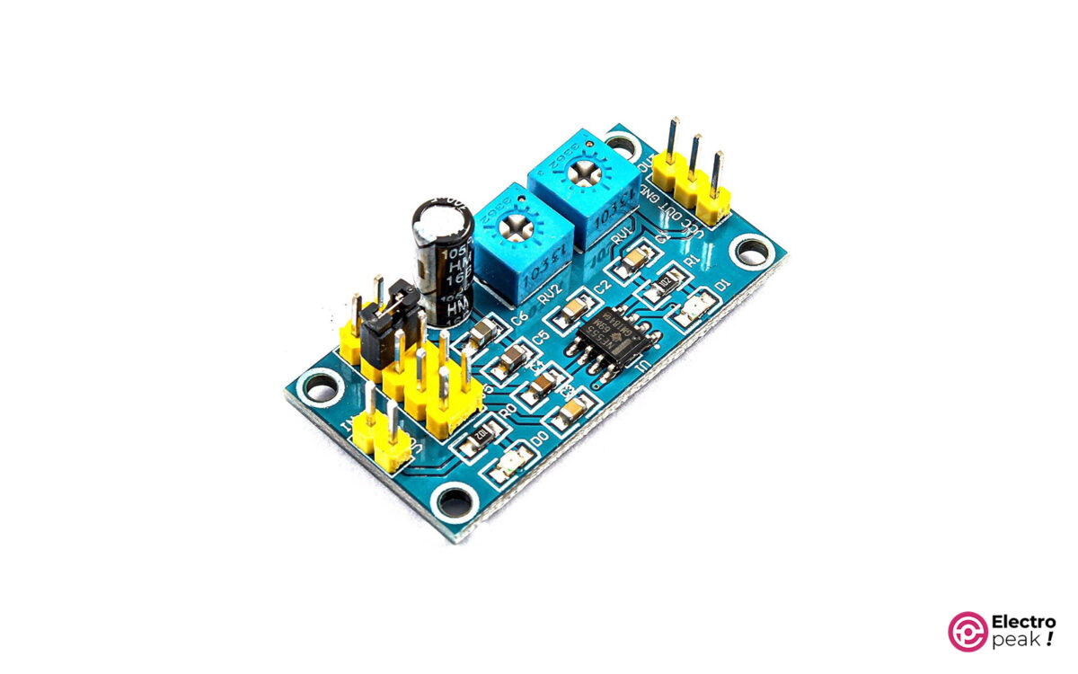
The following parameters are the same for all three models:
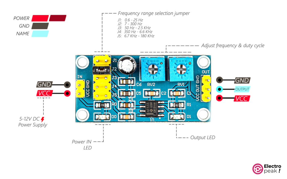
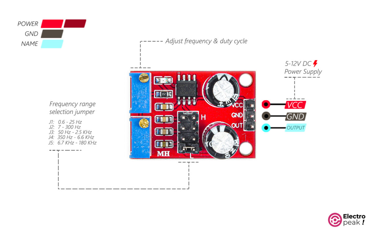
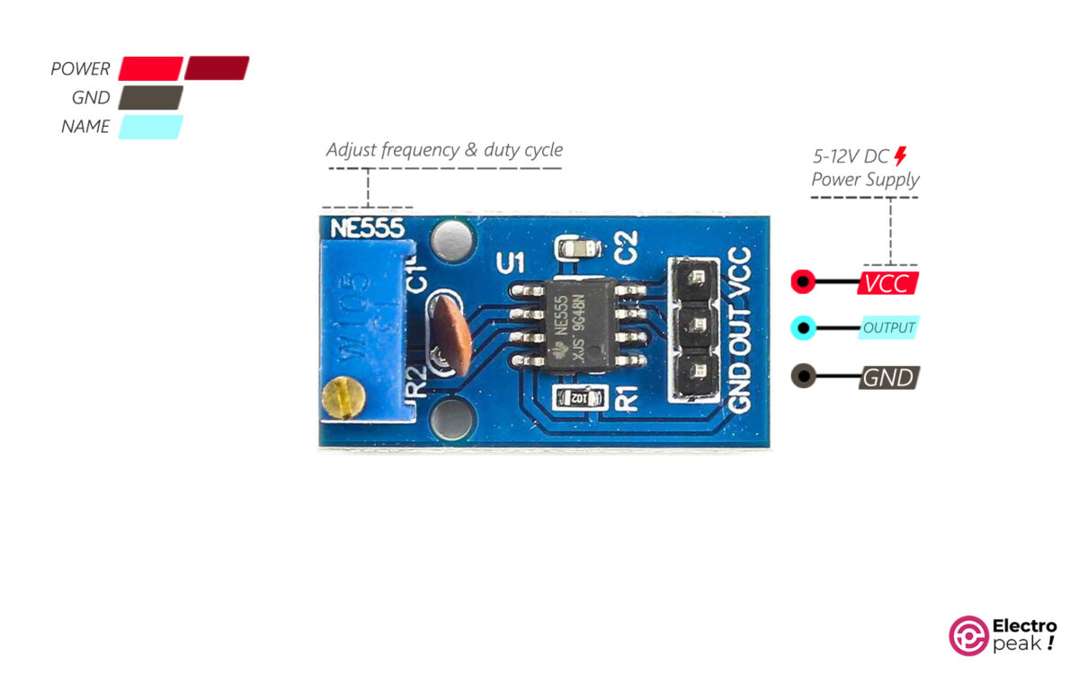
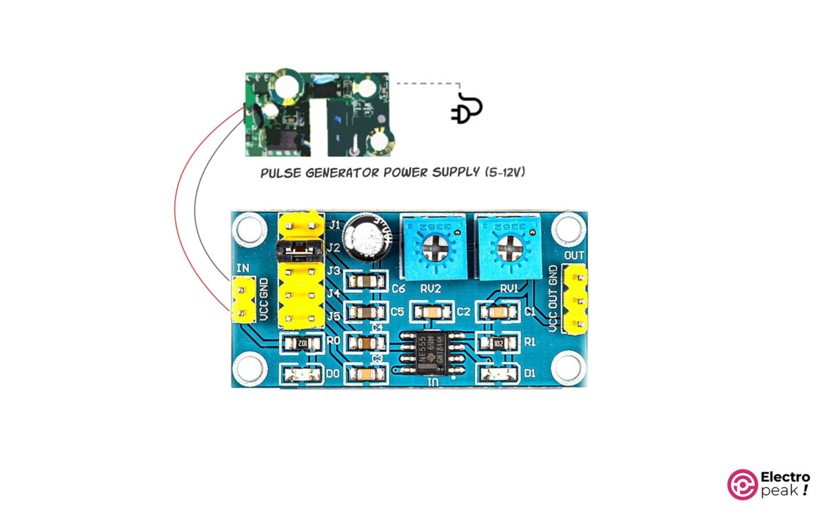
• Input voltage: 5 to 12 volts
• Output voltage: 4.2 to 11.6 volts
• Output voltage offset: between 0.6 and 0.8 volts
• Main chip: NE555 IC
• Current consumption (input): more than 100 mA
• Maximum output current: 15 mA (input voltage= 5 volts), 30 mA (input voltage= 12 volts)
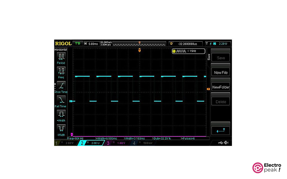
The three modules differ in terms of size, pulse frequency range, and duty cycle, which we mentioned earlier.
For more detailed information about how the NE555 IC works, you can refer to the Datasheet.

NE555 Modules Pinout

• VCC: module power supply (input voltage)
• GND: Ground
• OUT: output pin of the pulse
The jumpers for selecting frequency:
J1: 0.6Hz – 25Hz
J2: 7Hz – 300Hz
J3: 50Hz – 2.5KHz
J4: 350Hz – 6.6KHz
J5: 6.7KHz – 180KHz

NE555 Pulse Generator Module Pinout (1)
NE555 Pulse Generator Module Pinout (3)

Required Materials

Hardware Components

NE555 Time/Pulse Generator Module* × 1
PWM Switch Module × 2
12V Fan × 3
Jumper Wire × 4
5 to 12V Power Supply × 5

* Purchase one according to the module specifications and what you need.

How to Use NE555 Pulse Generator Module

We interface the NE555 module for two cases: (1) a simple test to ensure the module’s health, and (2) to control the speed of a DC motor.
The pulse generator modules mentioned above have the same wiring diagram and applications.
We’ll focus on one of these modules, but the process for the other two is pretty much the same.

Pulse Generator Module Test

To do a simple test, connect the circuit as shown below. The supply voltage must range between 5 and 12 volts and the current must be at least 150 mA.

NE555 Pulse Generator Module (Simple Test)

Here, using a certain jumper or turning the potentiometers should change the brightness of LED D1. The LED should blink slowly at low frequencies, and blink faster at higher frequencies.
To monitor the output frequency and duty cycle, use an oscilloscope.
Here’s how to connect the oscilloscope probe to observe the output:

NE555 Pulse Generator Module (Output)

On the oscilloscope screen, you’ll see a square wave similar to the image below. Using a specific jumper or turning the potentiometers will change the wave’s frequency and duty cycle.
For example, the images below show the module output in three different scenarios based on our own test results.

Minimum Frequency

The above image shows the lowest frequency produced by the module. The number at the bottom left of the image—431mHz—is the frequency of the voltage waveform. In addition, jumper J1 is connected and the potentiometers are set to their maximum position (fully clockwise).

The image above is for when the jumper J3 is connected.

Maximum Frequency

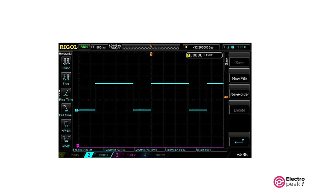
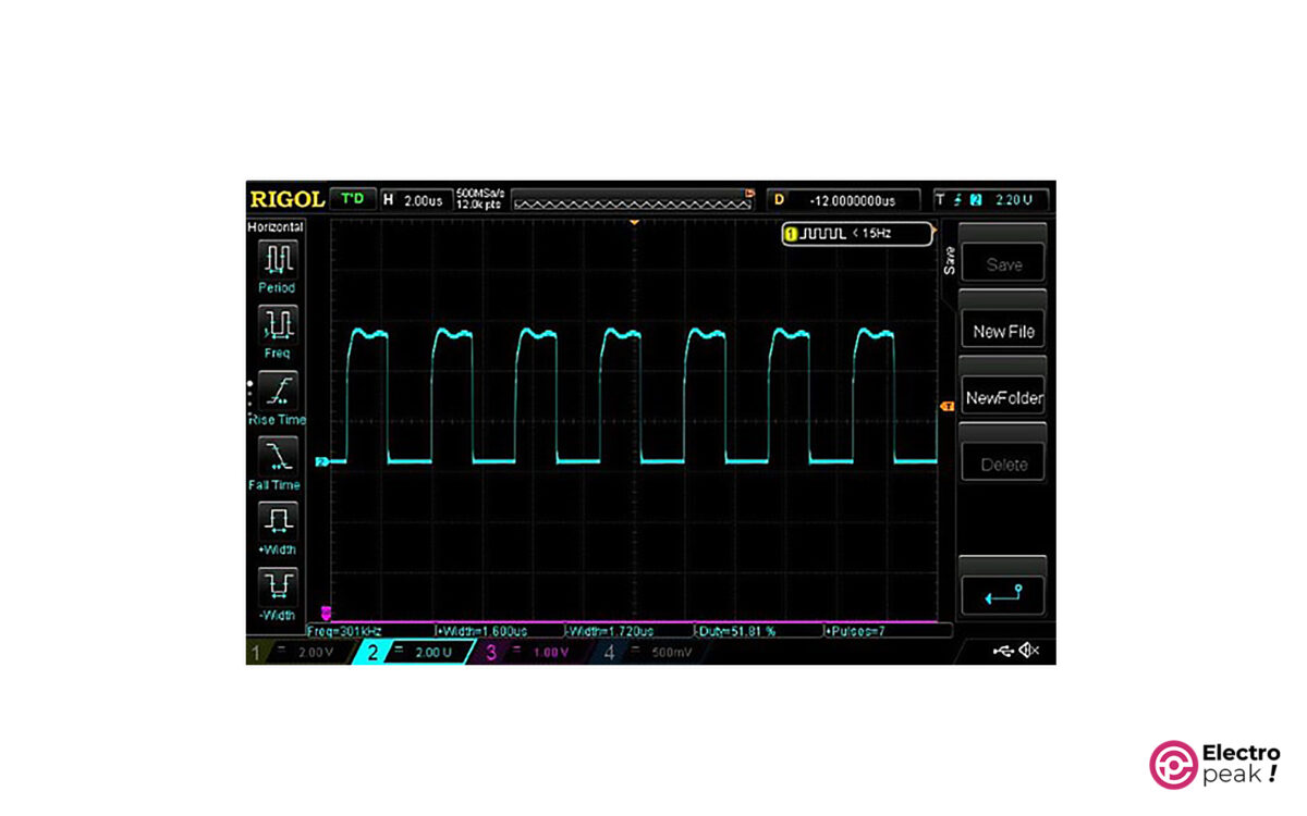
And, in the last image above, jumper J2 is connected and the potentiometers are set to their maximum position (fully counterclockwise). This square wave is the highest frequency produced by the module with a value of 301kHz.
If you’d like to see more examples, feel free to check out the file below, which shows the test results for this module.

Motor Speed Control with NE555 Pulse Generator and MOSFET Switch

The maximum output current of the pulse generator module is 15 mA. This value is barely enough to light up an LED. Therefore, we can’t use the pulse produced by the module directly as an output but rather as an excitation signal for the switching circuits.
There are many different switching circuits, most of which are designed based on transistors. These circuits help to run and control an actuator such as a motor (with high amounts of voltage and current) by a weak excitation signal (with low amounts of current and voltage). We can generate the excitation signal by a microcontroller or any other circuit such as a pulse generator module.
First, let’s quickly look at one type of switching circuit that has a MOSFET:

MOSFET as Switch

The circuit below shows how a MOSFET is often used in switching circuits.

MOSFET as a Switch

In the circuit above, as the input voltage (Vin) increases, so does the voltage of the transistor’s gate pin (G), activating the transistor. This means that, now, there is a connection between the drain pin (D) and the source pin (S), allowing the current to flow from VDD to Gnd; that is, the lamp (or any other consumer in the circuit) turns on.
The Vin pin should be connected to a microcontroller or any other circuit that can provide the required excitation signal for the transistor. In this case, the consumer current can no longer pass through the Vin pin. In addition, the VDD that supplies power for the consumer can be much higher than the excitation voltage. (Because different transistors have various voltages and currents for drain-source and excitation signal, you should refer to the transistor datasheet to get the exact values for each model.)
For example, suppose you want to activate a 12V motor with Arduino. Since the voltage of the Arduino pins is 5V and the current passing through them can be no more than 30 mA, it’s not possible to connect the Arduino pin directly to the motor pin as an output. Solution: use the switching circuit mentioned above. All you need to do is simply connect the Arduino output pin to the Vin and the VDD to the 12V power supply and replace the lamp with a motor. This way, we can activate the 12V motor circuit with the 5V Arduino signal. After that, we will control the speed of the DC motor using a power-switching module.
In this example, we use the HW-517 MOSFET Switch Module as the switching circuit. This module has two AOD4184A Power MOSFETs in parallel, providing a maximum current of 15A. The HW-517 module operates with an excitation voltage between 3.3 and 20 volts, and its output voltage should range from 5 to 36 volts.

Wiring

NE555 Pulse Generator Module Circuit

In the above circuit, the output of the pulse generator module is connected to the switch module as an excitation signal. The MOSFETs are turned on and off with the same frequency and duty cycle as the excitation signal, switching on and off the connection between the fan and the right power supply. With this method, we can control the average voltage applied to the fan by the frequency and duty cycle—in other words, we can control its speed.
The power supply connected to the pulse generator must be a 5-to-12V power supply with a current higher than 150mA. The power supply on the right side should have a voltage between 5 and 36 volts, the exact value of which is determined by the operating voltage of the consumer (in this case, the fan). Make sure to select an appropriate current based on the actuator’s power consumption.
You can also use the above circuit to control the color and light intensity of RGB LEDs.

What’s Next?

Try to make an RGB color controller using 3 pulse generator modules and 3 switch modules, as in the second example, and adjust the color and brightness of an RGB LED String.
Make a digital-to-analog voltage converter using a pulse generator module and an RC circuit.

Liked What You See?​
Get Updates And Learn From The Best​

Leave a Reply

Your email address will not be published. Required fields are marked *