

Introduction
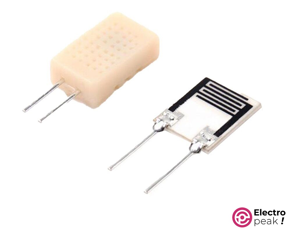
Would you like to unlock the full potential of a sensor? Do you enjoy challenging your limits? Well, that’s exactly what the HR202L sensor offers! HR202L is a variable capacitor with a non-linear logarithmic behavior, whose values depend highly on the ambient temperature.
Whether you’re new to Arduino or have been using it for a while, this guide will provide you with everything you need to get started with the HR202L sensor. By following clear instructions, practical examples, and professional tips, you’ll soon be able to use the full potential of this sensor and create innovative, cutting-edge applications.
What You Will Learn
- How to read the logarithmic output of the HR202L sensor
- How to Increase the measurement accuracy of the HR202L sensor
How HR202L Sensor Works?
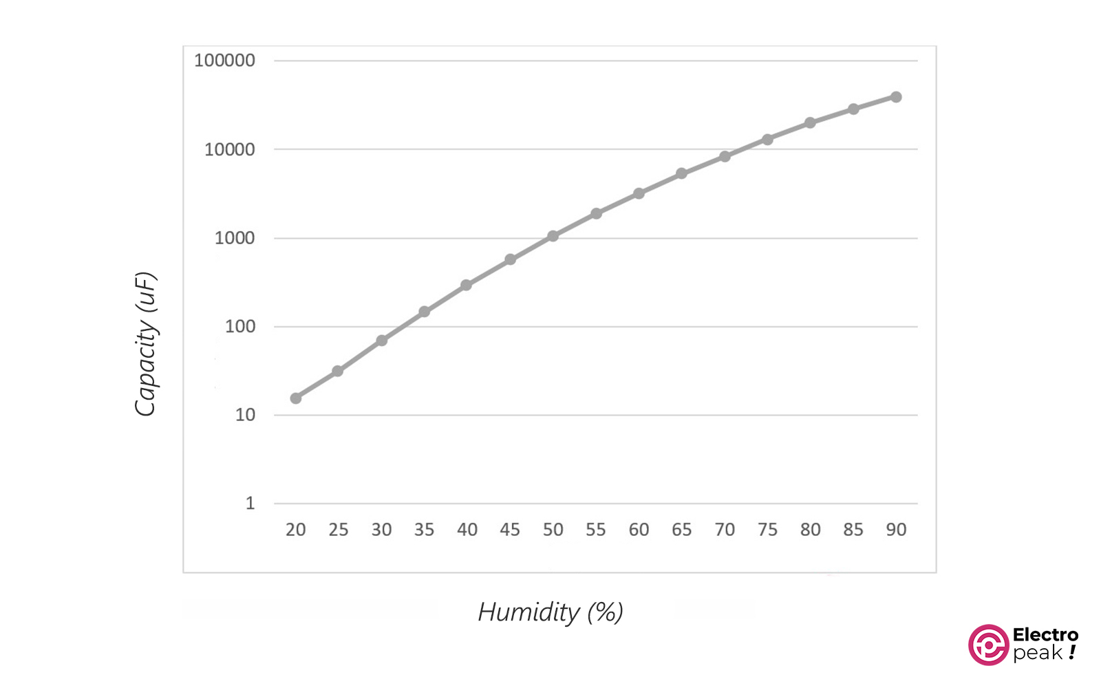
To understand how the HR202L sensor functions, it’s important to have a basic knowledge of the capacitive humidity sensor.
This sensor consists of two electrodes that are separated by a moisture-sensitive dielectric material. When the humidity in the environment changes, so does the dielectric constant of the material, which then affects the capacitance.
To measure the HR202L sensor capacitance, there are two basic problems:
First: The low capacitance in low humidity; this value can be about 1.5 pF. To measure the capacitance of such a capacitor, we need requirements that most Arduino boards do not have (such as a high ADC sampling rate).
Second: the capacitance range of the HR202L sensor varies from a few pF to several hundred nF. We cannot measure this range with a simple circuit.
To understand the performance of the HR202L sensor, let’s take a look at the datasheet. In the datasheet, you’ll see the following logarithmic curve. This curve shows the impedance of the sensor at a temperature of 25 degrees and a frequency of 1 kHz.

According to the datasheet, the sensor output is logarithmic, non-linear, and dependent on temperature.
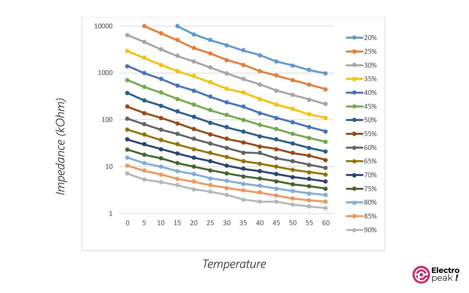
In the figure below, you can see the impedance of the HR202L sensor at different temperatures.

In the above figure, the HR202L sensor measures humidity and temperature in a range of 0 to 60 °C with 5-degree intervals, and the values are displayed in kΩ units. The impedance of this sensor varies significantly at different temperatures, so it’s important to consider this parameter for accurate humidity calculations.
Well, if you consider all these issues and the mentioned tips for measuring the sensor capacitance, you will understand the situation!
But, we will teach you how to solve these issues.
HR202L Applications
The HR202L sensor has a wide range of applications in various industries, including:
- Weather monitoring systems: By measuring humidity and temperature, you can have valuable data for predicting weather patterns and monitoring environmental conditions. This information is useful for weathermen, farmers, and researchers to make better decisions and take necessary actions.
- Automated Greenhouse: By monitoring humidity and temperature values inside a greenhouse, you can have the optimal growth conditions for plants. Integrating the sensor with actuators and controllers enables the automatic adjustment of ventilation, irrigation, and heating systems, resulting in an ideal environment for plant growth.
- HVAC systems (heating, ventilation, and air conditioning): By constantly monitoring humidity and temperature values in buildings, we can adjust the HVAC system to maintain a comfortable and healthy indoor environment.
Required Materials
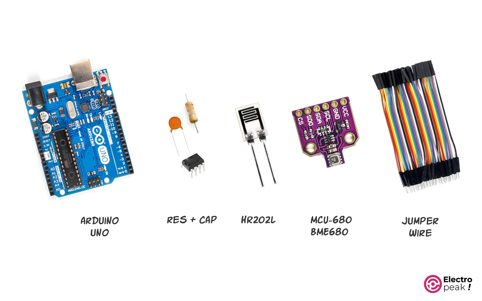
Hardware Components
***: You can replace this module with any other temperature sensor that can measure in degrees Celsius.
Software
Common Issues of Using HR202L Humidity Sensor
We discussed earlier about the challenges related to measuring the output of the HR202L sensor. Now, we will briefly revisit these common issues and provide their solutions.
Issues
1- Low capacitance: As mentioned earlier, at 15 °C (the fourth curve) and 20% humidity, for example, the impedance of this component is around 10 MΩ, resulting in a capacitance value of around 16 pF. It’s too small for conventional measurement methods.
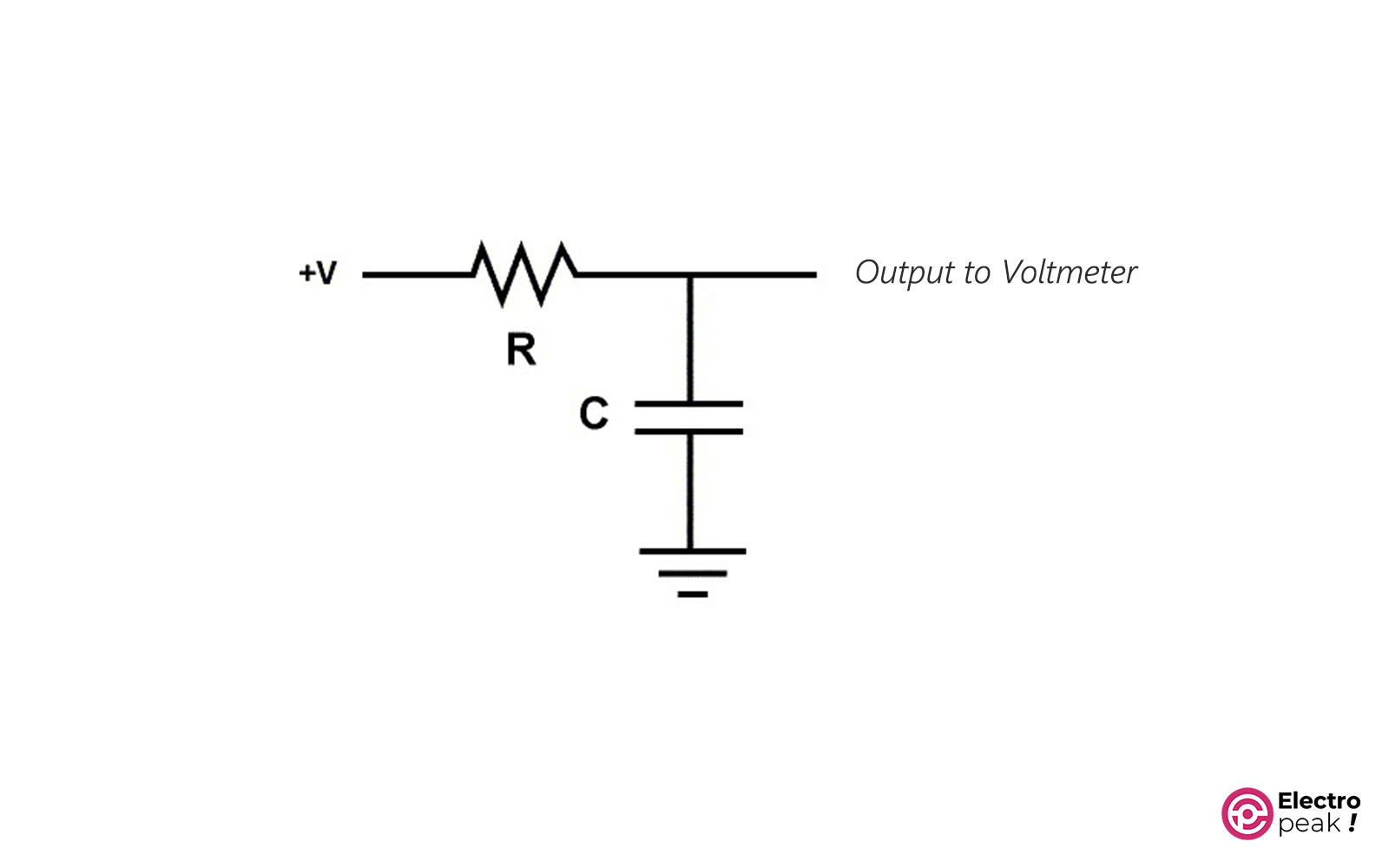
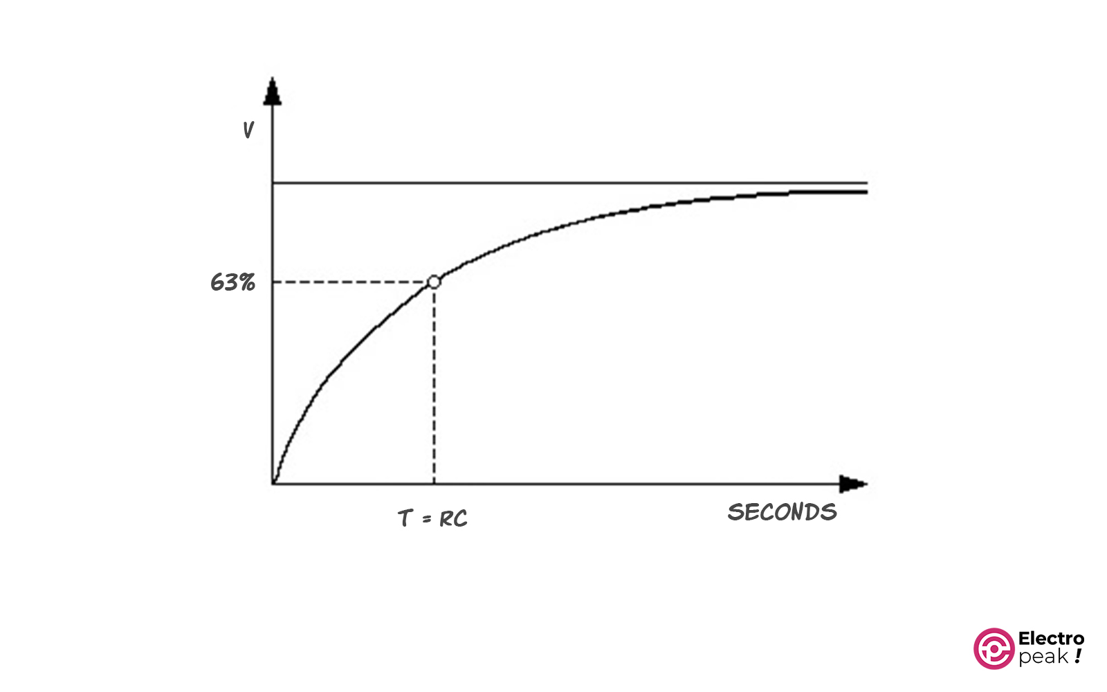
In the conventional method of measuring capacitance, we measure the charging time of the capacitor by a resistor connected to one of its terminals. The product of the resistance value and the capacitance is equal to the time when the capacitor is charged up to 63% of the rated voltage. The accuracy of this measurement depends on the sampling rate and resolution of the analog-to-digital converter (ADC).
However, the Arduino’s ADC has a sampling frequency of 9.6 Hz, which is not suitable for measuring such a small capacitor that charges so quickly. To measure a 16pF capacitor using this ADC with a 5% accuracy, you would need a resistance of at least 130 GΩ!
2- Wide range of capacitance variations: As mentioned, the capacitance of the HR202L sensor can vary from a few pF to several hundred nF. Using the usual method, you would only be able to measure the capacitance within a small range of humidity. For example, suppose we have a series capacitor-resistor circuit. If the resistance value is chosen to measure a capacitor of several nF, it would take a very long time to charge a several-hundred nF capacitor.
3- Highly dependent on temperature: As mentioned before, the capacitance-temperature curve of this sensor shows that changing the temperature from 0 to 60 °C in an environment with 50% humidity can cause the impedance to change from 370 kΩ to 21 kΩ. This means that the capacitance changes from 0.43 nF to 7.6 nF, resulting in an error of 1667%!
The figure below shows how the temperature affects the impedance of the HR202L sensor. On the right side of the figure, you can see the humidity level for each curve.
Solutions
Solution for Problems 1 and 2:
To solve the problems 1 and 2, we can indirectly measure the capacitance, converting it into another parameter. To do this, we can use the NE555 timer IC. Using the circuit provided in the wiring section, we can convert the variable capacitance into a variable frequency and measure it with Arduino. Through mathematical calculations, we can then determine the capacitance based on the frequency. Additionally, we can obtain the humidity by calculating the sensor impedance at a frequency of 1 kHz using the datasheet curve.
Solution for Problem 3:
To correct the error caused by temperature, we need to use a temperature sensor. Based on the temperature at the moment of measuring, we use a corresponding curve to calculate the humidity. In this tutorial, the BME680 sensor is used for this purpose. However, you can use any other analog or digital sensor that is more cost-effective.
How to Interface the HR202L Humidity Sensor with Arduino
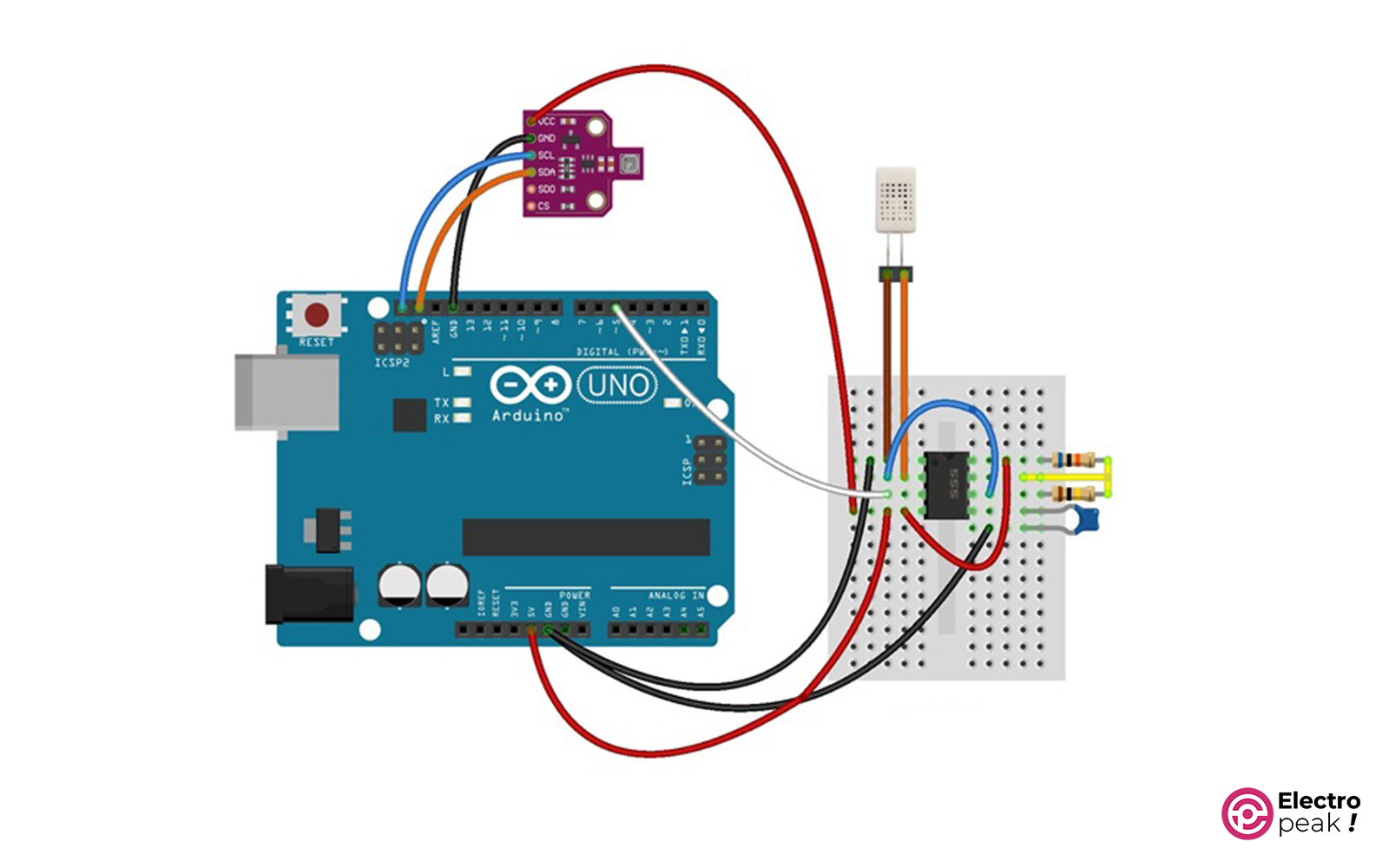
Step 1: Wiring
Connect the components as shown in the image below.
Step 2: Code
First, download and install the FreqCounter and Adafruit BME680 libraries, and then upload the code below to your Arduino.
| Board | The input frequency pin | Pins where analogWrite() doesn't work |
|---|---|---|
| Arduino Uno | 5 | 3,9,10,11 |
| Arduino Mega | 47 | 9,10,44,45,46 |
| Arduino Leonardo | 12 | 6,9,10,13 |
#include <FreqCounter.h>
#include <stdlib.h>

#include <Wire.h>
#include <Adafruit_Sensor.h>
#include "Adafruit_BME680.h"

Adafruit_BME680 bme; // I2C

#define countdelay 1 // measurement delay
#define calibration 0 // adjusts frequency for variation in Arduino
#define gatetime 100 // gate time in milliseconds
#define onems 1000 // alias for 1000 milliseconds

char units[][5] = {"Hz", "KHz", "MHz"}; //units of frequency to be used later
float omega = 2 * PI*1000;
float impedance;


void setup() {
 Serial.begin(9600); // initialize the LCD
 while (!Serial);
 Serial.print("** HR202L Humidity Sensor **"); //initial message
 if (!bme.begin()) {
 Serial.println("Could not find a valid BME680 sensor, check wiring!");
 while (1);
 }

 // Set up oversampling and filter initialization
 bme.setTemperatureOversampling(BME680_OS_8X);
 bme.setHumidityOversampling(BME680_OS_2X);
 bme.setPressureOversampling(BME680_OS_4X);
 bme.setIIRFilterSize(BME680_FILTER_SIZE_3);
 bme.setGasHeater(320, 150); // 320*C for 150 ms
 delay(100); //100ms startup delay
}

void loop() {
 if (! bme.performReading()) {
 Serial.println("Failed to perform reading :(");
 return;
 }
 float temp = bme.temperature;
 unsigned long Fcalc = 0;
 float Fval;
 float capacitance;
 float Humidity;


 FreqCounter::f_comp = calibration; // calibrate with known source
 FreqCounter::start(gatetime); // count pulses for specified gating period
 while (FreqCounter::f_ready == 0)
 Fcalc = FreqCounter::f_freq;
 delay(countdelay);
 Fval = (float) Fcalc * (onems / gatetime); // scale the input


 capacitance = (1.44 * 1000000000000) / (260000 * Fval);//capacitance in pF
 impedance = 1/ (omega * capacitance)*1000000000000; //calculating the Impedance in Ohm

 if (temp > 0 && temp <= 5)
 Humidity = (6.8062 - log10(impedance)) / 0.04925 + 30;
 else if (temp > 5 && temp <= 10)
 Humidity = (7 - log10(impedance)) / 0.05039 + 25;
 else if (temp > 10 && temp <= 15)
 Humidity = (6.8451 - log10(impedance)) / 0.04882 + 25;
 else if (temp > 15 && temp <= 20)
 Humidity = (7 - log10(impedance)) / 0.04854 + 20;
 else if (temp > 20 && temp <= 25)
 Humidity = (6.8261 - log10(impedance)) / 0.04725 + 20;
 else if (temp > 25 && temp <= 30)
 Humidity = (6.699 - log10(impedance)) / 0.04854 + 20;
 else if (temp > 30 && temp <= 35)
 Humidity = (6.5911 - log10(impedance)) / 0.04561 + 20;
 else if (temp > 35 && temp <= 40)
 Humidity = (6.4771 - log10(impedance)) / 0.04537 + 20;
 else if (temp > 40 && temp <= 45)
 Humidity = (6.3802 - log10(impedance)) / 0.04464 + 20;
 else if (temp > 45 && temp <= 50)
 Humidity = (6.2430 - log10(impedance)) / 0.04268 + 20;
 else if (temp > 50 && temp <= 55)
 Humidity = (6.1614 - log10(impedance)) / 0.04244 + 20;
 else if (temp > 55 && temp <= 60)
 Humidity = (6.0607 - log10(impedance)) / 0.04163 + 20;
 else if (temp > 60 && temp <= 65)
 Humidity = (5.9867 - log10(impedance)) / 0.04104 + 20;
 else {
 Serial.print("Out of Range");
 while (1);
 }
 Serial.print("Temp: ");
 Serial.print(temp);Serial.print('\t');
 Serial.print("Cap(pF): ");
 Serial.print(capacitance);Serial.print('\t');
 Serial.print("Humidity(%): ");
 Serial.print(Humidity);Serial.print('\t');
 Serial.print("Freq(Hz): ");
 Serial.println(Fval);
}
Code Cracking
Now, let’s break down the code:
1. Loading the required libraries
#include <FreqCounter.h>
#include <stdlib.h>

#include <Wire.h>
#include <Adafruit_Sensor.h>
#include "Adafruit_BME680.h"
2. Creating an instance for the BME680 sensor
Adafruit_BME680 bme;
3. Defining parameters for the Arduino counter
- countdelay: the time required to measure the frequency
- calibration: frequency calibration for Arduino if there is an error
- gatetime: a fixed duration for pulse counting
- onems: the time passed for Arduino in actual 1000 milliseconds
#define countdelay 1 // measurement delay
#define calibration 0 // adjusts frequency for variation in Arduino
#define gatetime 100 // gate time in milliseconds
#define onems 1000 // alias for 1000 milliseconds
4. Setup() function: Activating serial communication, communicating with BME680, and configuring its filters.
void setup() {
  Serial.begin(9600); // initialize the LCD
  while (!Serial);
  Serial.print("** HR202L Humidity Sensor **"); //initial message
  if (!bme.begin()) {
    Serial.println("Could not find a valid BME680 sensor, check wiring!");
    while (1);
  }

  // Set up oversampling and filter initialization
  bme.setTemperatureOversampling(BME680_OS_8X);
  bme.setHumidityOversampling(BME680_OS_2X);
  bme.setPressureOversampling(BME680_OS_4X);
  bme.setIIRFilterSize(BME680_FILTER_SIZE_3);
  bme.setGasHeater(320, 150); // 320*C for 150 ms
  delay(100); //100ms startup delay
}
5. Loop() function:
- Reading temperature from the output data of the BME680 sensor (you can use any other sensor).
if (! bme.performReading()) {
    Serial.println("Failed to perform reading :(");
    return;
  }
  float temp = bme.temperature;
- Measuring the input signal frequency of the NE555 timer
We Measure the number of rising pulses within a specific time unit defined in “gatetime” and convert it to pulses per second (Hz).
  FreqCounter::f_comp = calibration; // calibrate with known source
  FreqCounter::start(gatetime); // count pulses for specified gating period
  while (FreqCounter::f_ready == 0)
    Fcalc = FreqCounter::f_freq;
  delay(countdelay);
  Fval = (float) Fcalc * (onems / gatetime); // scale the input
- Calculating the capacitance of the HR202L sensor
Here, we obtain the number 260000 from the following equation:
R1 + 2 × R2
capacitance = (1.44 * 1000000000000) / (260000 * Fval); //calculating the Capacitance in pF
- Calculating the impedance of the HR202L sensor
As you know, the impedance of a capacitor is obtained from the following equation:
Z = 1 / (ω × c)
impedance = 1/ (omega * capacitance)*1000000000000; //calculating the Impedance in Ohm
- Using the measured temperature by BME680 to accurately calculate humidity
Each of the following equations represents one of the lines of the impedance curve. Based on the temperature value during the measurement, we obtain the sensor impedance using one of the following equations.
if (temp > 0 && temp <= 5)
 Humidity = (6.8062 - log10(impedance)) / 0.04925 + 30;
 else if (temp > 5 && temp <= 10)
 Humidity = (7 - log10(impedance)) / 0.05039 + 25;
 else if (temp > 10 && temp <= 15)
 Humidity = (6.8451 - log10(impedance)) / 0.04882 + 25;
 else if (temp > 15 && temp <= 20)
 Humidity = (7 - log10(impedance)) / 0.04854 + 20;
 else if (temp > 20 && temp <= 25)
 Humidity = (6.8261 - log10(impedance)) / 0.04725 + 20;
 else if (temp > 25 && temp <= 30)
 Humidity = (6.699 - log10(impedance)) / 0.04854 + 20;
 else if (temp > 30 && temp <= 35)
 Humidity = (6.5911 - log10(impedance)) / 0.04561 + 20;
 else if (temp > 35 && temp <= 40)
 Humidity = (6.4771 - log10(impedance)) / 0.04537 + 20;
 else if (temp > 40 && temp <= 45)
 Humidity = (6.3802 - log10(impedance)) / 0.04464 + 20;
 else if (temp > 45 && temp <= 50)
 Humidity = (6.2430 - log10(impedance) + 12) / 0.04268 + 20;
 else if (temp > 50 && temp <= 55)
 Humidity = (6.1614 - log10(impedance) + 12) / 0.04244 + 20;
 else if (temp > 55 && temp <= 60)
 Humidity = (6.0607 - log10(impedance) + 12) / 0.04163 + 20;
 else if (temp > 60 && temp <= 65)
 Humidity = (5.9867 - log10(impedance) + 12) / 0.04104 + 20;
 else {
 Serial.print("Out of Range");
 while (1);
 }
- Printing the calculated values in the serial monitor
  Serial.print("Cap(pF): ");
  Serial.print(capacitance);Serial.print('\t');
  Serial.print("Humidity(%): ");
  Serial.print(Humidity);Serial.print('\t');
  Serial.print("Freq(Hz): ");
  Serial.println(Fval);
The Humidity Measurement Results for HR202L
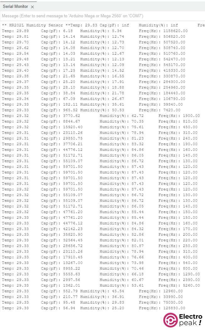
After programming your Arduino board, open the serial monitor window. Arduino will start reading the input frequency of NE555 and print the calculated data. Here’s an example output of the provided code shown in the image below.
What’s Next?
In this tutorial, you have learned how to correctly use the HR202L sensor, which is a logarithmic, non-linear, and temperature-dependent sensor. You have also learned how to convert the sensor signal to a format suitable for your microcontroller.
There are many other practical sensors that may be non-linear or logarithmic. This tutorial will make it easy for you to reach your goals effortlessly.

Comments (5)
Hello. Is it possible to get a further explanation, for the values used to define humidity in different temperatures?
I’m making a greenhouse project, where i’m using this humidity sensor, and i would like to present this circuit.
Hello,
In this article, we delve into the functionality of the HR202L sensor and compare its output with more precise sensors like the BME680.
If you require data from different sections of your greenhouse, I recommend utilizing an ESP8266 or ESP32 along with a DHT11, DHT22, or SHT sensor. This setup allows you to gather readings from various parts of your greenhouse and transmit the data to your base using the ESP’s network capabilities.
What is the value 1.44 when calculating the capacitance? Is it the capacitance on the HR202L or is it some constant? When i use 1.44 i get a reletive low humidity. If i change it to the messured capacitance on the HR202L i get at resonable humidity
The value of 1.44 represents the square of 2, which is used in calculating the charging time of a capacitor.
We are currently reviewing this article again, and if you have any additional information to contribute, please feel free to share it with us.
Hello! I worked a little with these sensors, and was a little surprised that the HR202 from Aliexpress and directly from AOSONG are different things, and the first are resistive, and the second are almost pure capacitance)) And that the measurement method from the datasheet from AOSONG does not work with them sensors, but with sensors from aliexpress – yes)) But both are nevertheless afraid of constant voltage and polarization, and in the circuit on NE555 there will always be a constant voltage equal to 1/2 Ucont on the sensor even when its capacitance is discharged((