
Overview
Thousands of cars are being stolen every day around the globe. So it is really important to protect and secure your car. In this tutorial we will use the SIM808 module to build a GPS car tracker.
If you are not willing to use a GPS read this article to find out how to detect location by GSM modules: (Using GSM with Arduino as an alternative for GPS).
What You Will Learn
- Get to know with the concept of GPS
- Get to know with the sim808 module
- Build a GPS car tracker
What is GPS and how does it work?
GPS stands for Global Positioning System, which designed and built in 1973 by the United States Department of Defense. Today, the use of GPS has become so common that almost all of us use this system daily.
The GPS system includes 24 satellites. For the car tracker project (or any other project) you need a GPS receiver to receive information sent from this satellite. All your GPS receiver has to do is identify four satellites and read information from them to calculate your position with a series of geometric relationships.
GPS can provide your position with very high accuracy, but the satisfaction of this accuracy depends on your GPS receiver, typical GPS modules have an accuracy of between 2 and 5 meters.
The most important information we can get from the GPS system are: longitude, latitude, speed, height and time in Greenwich Mean Time.
Ublox is a leading company in the industry of manufacturing GPS modules, but to receive GPS information, we can also use the SIM808 module manufactured by SIMCOM.
What is SIM808 module?
We usually used a series of SIM modules for sending and receiving SMS, making calls, using GPRS, etc., but the SIM808 module has a special feature and that is GPS receiver. This feature makes this module very useful for making all kinds of trackers. In this tutorial, you will learn how to connect SIM808 module and Arduino and make a car tracker.
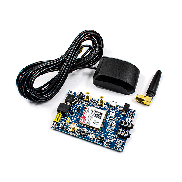
This module is provided in a package with GPS and GSM antennas as shown below.
SIM808 Module Pinout
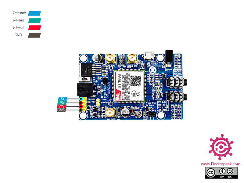
SIM808 module uses serial communication protocol to interface with Arduino. This module has 10 pins. 4 are the main pins and the rest are connected to those 4 pins.
4 Main Pins on the Left Side:
- TX: Transmitting Data
- RX: Receiving Data
- VIN: Input voltage (this pin is connected to the jack plug, and if the adapter is connected, no power needs to be supplied here.)
- GND: Ground
You can see the pinout of this module in the image below.
Required Material
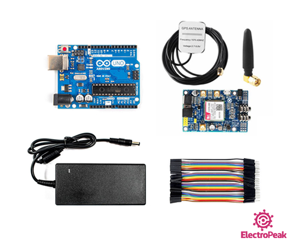
Hardware Components
Software Apps
Interfacing SIM808 Module with Arduino
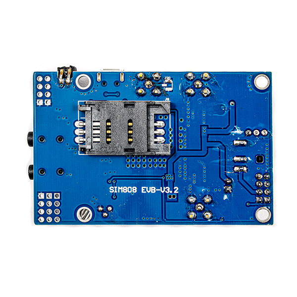
Connect GPS and GSM antennas and adapter to the module as shown below.
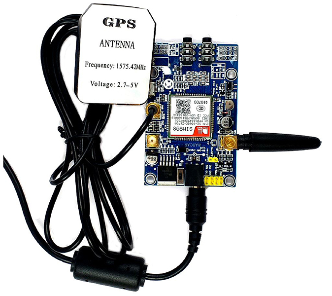
Insert the SIM card in the card slot in the back of the module.
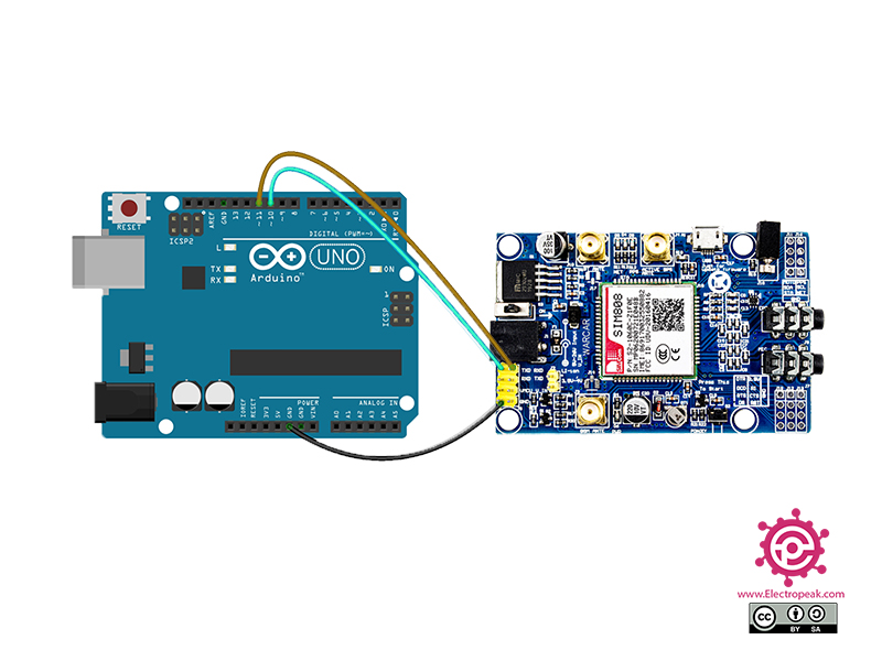
The following circuit shows how you should connect Arduino to SIM808 module. Connect wires accordingly.
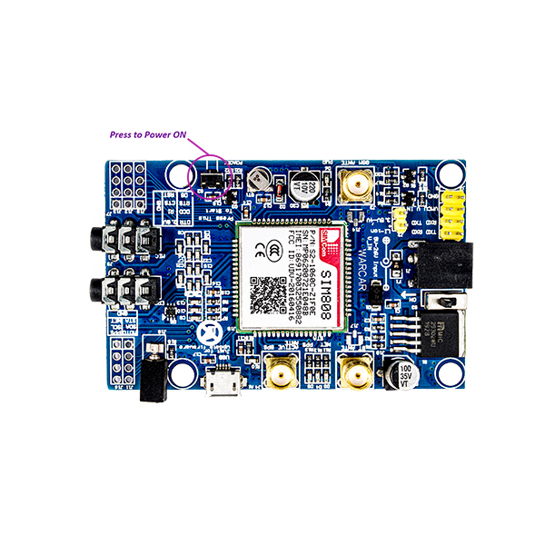
Note
After connecting the power supply, you must press the vertical button as shown below for at least one second.
Biuld a Car Tracker with Arduino and SIM808 Module
After completing the previous steps, now we are ready to build a tracker. In this project, we have used AT commands to write the code for the car tracking system. We have also used the TinyGPS ++ library to analyze the GPS data received from the SIM808 module.
In this project, the car tracking system first waits to receive a message. After that, it matches the received text with the predefined password. Then, if the password is correct, the tracker system will be activated, and it will obtain the vehicle location data. Finally, the Google Maps link will be sent to you.
Upload the following code to Arduino.
Code
/*
  Made on Jan 9, 2021
  By MehranMaleki @ Electropeak
  Home
*/

#include <SoftwareSerial.h>
#include <TinyGPS++.h>

boolean GetGPS_flag = false;
boolean Location_isValid_flag = false;
boolean Password_flag = false;


String value;
String phone_number;
String message_text;
String password = "Hello";
String Message;


#define PIN_TX    10
#define PIN_RX    11
SoftwareSerial mySerial(PIN_TX, PIN_RX);


// The TinyGPS++ object
TinyGPSPlus gps;

String SIM808(String value) {
  String Out;

  mySerial.println(value);
  delay(10);
  while (mySerial.available()) {
    Out = (mySerial.readString());
  }

  Out.trim();
  Out.remove(0, value.length() + 3);
  return Out;
}
String SIM808(String value, int count) {
  String Out;

  mySerial.println(value);
  delay(10);
  while (mySerial.available()) {
    Out = (mySerial.readString());
  }

  Out.trim();
  Out.remove(0, value.length() + 3 + count);
  return Out;
}

void setup() {
  mySerial.begin(9600);
  Serial.begin(9600);
}

void loop() {
  //******************* RECEIVING SMS *******************
  Serial.println("Start\n");

  Serial.println("Power Down The GPS");
  SIM808("AT+CGPSPWR=0");

  Serial.println("Check AT Connection");
  value = SIM808("AT");
  Serial.println(value);
  Serial.println("");

  Serial.println("Put The Module in SMS Text Mode");
  SIM808("AT+CMGF=1");
  delay(1000);


  Serial.println("Delete All Previous Messages");
  SIM808("AT+CMGD=1,4");
  delay(2000);

  value = SIM808("AT+CMGL=\"REC UNREAD\"");
  value = SIM808("AT+CMGL=\"REC UNREAD\"");
  value = SIM808("AT+CMGL=\"REC UNREAD\"");

  do {
    delay(2000);
    Serial.println("No new Messages Received");
    Serial.println("Check for New Messages!");
    value = SIM808("AT+CMGL=\"REC UNREAD\"");
    //Serial.println("end");
  } while (value == "OK");

  SIM808("AT+CMGL=\"REC UNREAD\"");
  Serial.println("Message Recieved");

  value = SIM808("AT+CMGL=\"ALL\"");
  Serial.println(value);
  phone_number = value;
  phone_number.remove(0, 20);
  phone_number.remove(15, phone_number.length());
  message_text = value;
  message_text.remove(0, 63);
  message_text.remove(message_text.length() - 6, message_text.length());

  Serial.println("Phone Number:");
  Serial.println(phone_number);

  Serial.println("Message Text:");
  Serial.println(message_text);


  if (message_text == password) {
    GetGPS_flag = true;
    Password_flag = true;
    Serial.println("password is correct!");
  }
  //******************* RECEIVING SMS END *******************


  //******************* GET GPS *******************
  if (GetGPS_flag) {
    do {
      Serial.println("Power Down The GPS");
      SIM808("AT+CGPSPWR=0");
      //Serial.println("end");

      Serial.println("Check The GPS Power");
      value = SIM808("AT+CGPSPWR?");
      value.remove(11, 17);
      Serial.println(value);
      //Serial.println("end");

      Serial.println("Power Up The GPS");
      SIM808("AT+CGPSPWR=1");
      //Serial.println("end");

      Serial.println("Disable The GPS Output");
      SIM808("AT+CGPSOUT=0");
      //Serial.println("end\n");

      Serial.println("Wait For The GPS To Find Location");
      while (!SIM808("AT+CGPSSTATUS?" , 13).startsWith("Location 3D Fix")) {
        Serial.println("Location Not Fixed Yet, Please Wait!");
        delay(2000);
      }
      Serial.println("Location Found!");
      Serial.println("end\n");


      //Get and Analyse The GPS Output
      Serial.println("Get and Analyse The GPS Output");
      String Out = "";
      mySerial.println("AT+CGPSOUT=2");

      delay(10);
      while (mySerial.available()) {
        mySerial.readStringUntil('\n');
        mySerial.readStringUntil('\n');
        Out = (mySerial.readStringUntil('\n'));  Out += "\r\n";
      }
      mySerial.println("AT+CGPSOUT=0");
      delay(100);
      mySerial.println("AT+CGPSOUT=32");
      delay(10);
      while (mySerial.available()) {
        mySerial.readStringUntil('\n');
        mySerial.readStringUntil('\n');
        Out += (mySerial.readStringUntil('\n'));  Out += "\r\n";
      }
      mySerial.println("AT+CGPSOUT=0");
      Out.trim();
      Serial.println(Out);
      Serial.println("");
      //GPS Output Analized


      int buffint = Out.length();
      char buff[buffint];
      Out.toCharArray(buff, buffint);
      const char *gpsStream = buff;

      while (*gpsStream)
        if (gps.encode(*gpsStream++))
          displayInfo();

      Serial.println("");
      Serial.println("");

      delay(100);
      if (gps.location.isValid())
      {
        Location_isValid_flag = true;
        Message = String(gps.location.lat(), 6);
        Message += ",";
        Message += String(gps.location.lng(), 6);
        Message += " ";
        Serial.println(Message);
      }
    } while (!Location_isValid_flag);

  }
  //******************* GET GPS END *******************


  //******************* SENDING SMS *******************
  Serial.println("Start Sending The SMS\n");


  Serial.println("Sending The SMS to");
  Serial.println(phone_number);

  SIM808("AT+CMGS=" + phone_number );
  delay(200);

  if (Password_flag == true) {
    mySerial.println("Open This Link:");
    mySerial.print("https://www.google.com/maps/place/");
    SIM808(Message);
  }
  else {
    mySerial.println("Password Incorrect! ");
  }
  Serial.println("Message Sent!");

  Serial.println("Delete All Previous Messages");
  SIM808("AT+CMGD=1,4");
  delay(2000);
  //******************* SENDING SMS END*******************

  //reinitializing flags
  GetGPS_flag = false;
  Location_isValid_flag = false;
  Password_flag = false;
}


void displayInfo()
{
  Serial.print(F("Location: "));
  if (gps.location.isValid())
  {
    Serial.print(gps.location.lat(), 6);
    Serial.print(F(","));
    Serial.print(gps.location.lng(), 6);
  }
  else
  {
    Serial.print(F("INVALID"));
  }

  Serial.println();
}

char * floatToString(char * outstr, double val, byte precision, byte widthp) {
  char temp[16];
  byte i;

  // compute the rounding factor and fractional multiplier
  double roundingFactor = 0.5;
  unsigned long mult = 1;
  for (i = 0; i < precision; i++)
  {
    roundingFactor /= 10.0;
    mult *= 10;
  }

  temp[0] = '\0';
  outstr[0] = '\0';

  if (val < 0.0) {
    strcpy(outstr, "-\0");
    val = -val;
  }

  val += roundingFactor;

  strcat(outstr, itoa(int(val), temp, 10)); //prints the int part
  if ( precision > 0) {
    strcat(outstr, ".\0"); // print the decimal point
    unsigned long frac;
    unsigned long mult = 1;
    byte padding = precision - 1;
    while (precision--)
      mult *= 10;

    if (val >= 0)
      frac = (val - int(val)) * mult;
    else
      frac = (int(val) - val ) * mult;
    unsigned long frac1 = frac;

    while (frac1 /= 10)
      padding--;

    while (padding--)
      strcat(outstr, "0\0");

    strcat(outstr, itoa(frac, temp, 10));
  }

  // generate space padding
  if ((widthp != 0) && (widthp >= strlen(outstr))) {
    byte J = 0;
    J = widthp - strlen(outstr);

    for (i = 0; i < J; i++) {
      temp[i] = ' ';
    }

    temp[i++] = '\0';
    strcat(temp, outstr);
    strcpy(outstr, temp);
  }
  return outstr;
}
At the beginning of this code, the password is specified. By sending the correct password to the car tracking system, a text message will be sent to you including the car Google Maps link.
The Google Maps link is similar to this:
https://www.google.com/maps/place/35.705936,51.391628
Click on the link, then you can see the car location in the Google Maps website.
If the password is incorrect, a text message will be sent to you including: “The password is incorrect.”
What’s Next?
- Upload the received information to the server.

Comments (18)
Thanks a lot you’ve been very helpful. But on my end after sending the correct password am not receiving the text message at all.
Hi, you’re quite welcome. Glad it’s been helpful for you.
And about your problem, it can actually be related to a handful of thing. First of all, what happens when you send a wrong password? If it still doesn’t send you any text, the GPS of the module might have not run yet. Note that the GPS of these modules are designed for outdoor applications, so if you’re inside your house, the GPS can’t start running. Also, it may take a while for the module to connect to the global GPS network. So, to wrap it up, try the project outdoors. And after powering up the sytem, give it a few minutes to make sure it has successfully connected to the GPS network. And then, send the password to it.
Hope you can get it up and running! Good luck.
Hi, I also had the same problem, I solved it by replacing this:
if (Password_flag == true) {
mySerial.println(“Open This Link:”);
mySerial.print(“https://www.google.com/maps/place/”);
SIM808(Message);
}
with this:
if (Password_flag == true) {
mySerial.println(“Open This Link:”);
mySerial.print(“https://www.google.com/maps/place/”);
mySerial.println(Message);
mySerial.println((char)26);
SIM808(Message);
}
Hi Mehran, please give me your email, I have some question. thank you
hello and thank for your site .
I used arduino pro mini and I do not know which pin connect to the sim 808 .
pin10——-tx
pin11——-rx
gnd ——–gnd
vcc ——– vcc
or
pin10——-rx
pin11——-tx
gnd ——–gnd
vcc ——– vcc
please help me
Hi dear
below is right :
pin10——-tx
pin11——-rx
gnd ——–gnd
vcc ——– vcc
Hi!
I got it to run – finally. But not on my Uno as planned but on a Mega. There it works fine. I found out, how to read out any information supplied by the gps. Now i am taking my first steps in using the gsm-part. After that i want to check about the BT-Option. It´s not mentioned anywhere, but there is an antenna for BT… Getting info about commands would be cool.
🙂
Hi dear
you can find how to use BT Command from here
https://www.youtube.com/watch?v=zdQb8r2xRK8
I was looking at code and wondered were to put phone # or how do i call the simcard
Hi Elwood,
After compiling and uploading the code, you will need to send an SMS to the module with the default password “Hello” as the message text. Arduino will use this SMS to set the Admin number.
I am using ATMEGA 2560 and SIM 808 Robotshop, mySerial does not print anything. However, I am not sure what the correct “myserial” ports are. The code works until it has to read a serial output from our board.
Hi Ibraheem,
The issue might be because your board is a shield for Arduino Uno. There is a selector on it to connect between D0, D1, and D7, D8. In this case, you should set it to D7, D8 and configure these two lines:
#define PIN_TX    8

#define PIN_RX    11
to
#define PIN_TX    7

#define PIN_RX    8
If it still doesn’t work, try swapping the numbers 8 and 7.
The ‘mySerial’ is a name for the ‘SoftwareSerial’ library that can be used on all types of Arduino (Arduino Mega 2560 has 3 external Serial ports too, but you are using a shield and it’s not connected to these pins).”
what sim card do you use?
Hello,
this model, like all SimCom models, is compatible with T-Mobile in any era.
Thank you for this good solution:
I used arduino Uno.
My problem : the module don’t send me message.
Hello, this article is being updated to address this issue. Additionally, due to the limited processing power of the Arduino Uno, we are considering updating the project to use either an Arduino Mega or an ESP32.
You can access the files for the updated code from this link. (base of PlatformIO)
Hello, code is working and it prints the location correctly, but I did not recieve a sms, what might be the problem? Thanks!
Hello, this article is being updated to address this issue. Additionally, due to the limited processing power of the Arduino Uno, we are considering updating the project to use either an Arduino Mega or an ESP32.
You can access the files for the updated code from this link. (base of PlatformIO)