
Introduction
If you are interested in electronics, you have probably dealt with an oscilloscope. This device is a crucial tool for analyzing circuit performance. Most professional oscilloscopes, however, are often large, heavy, and expensive.
In this tutorial, we will show you a practical and affordable solution for building your own oscilloscope and logic analyzer. All you need is a Raspberry Pi Pico/Pico W and an Android app called Scoppy.

This oscilloscope can connect to an Android device, giving you access to a wide range of features. With Scoppy, you can analyze waveforms and troubleshoot circuits. These capabilities allow you to make informed decisions and achieve your desired results.
Whether you are an experienced electronics enthusiast or a beginner looking for DIY projects, this tutorial will help you use Scoopy and bring your ideas to life.
What You Will Learn
- Introduction to Raspberry Pi Pico
- Building an oscilloscope with Raspberry Pi Pico
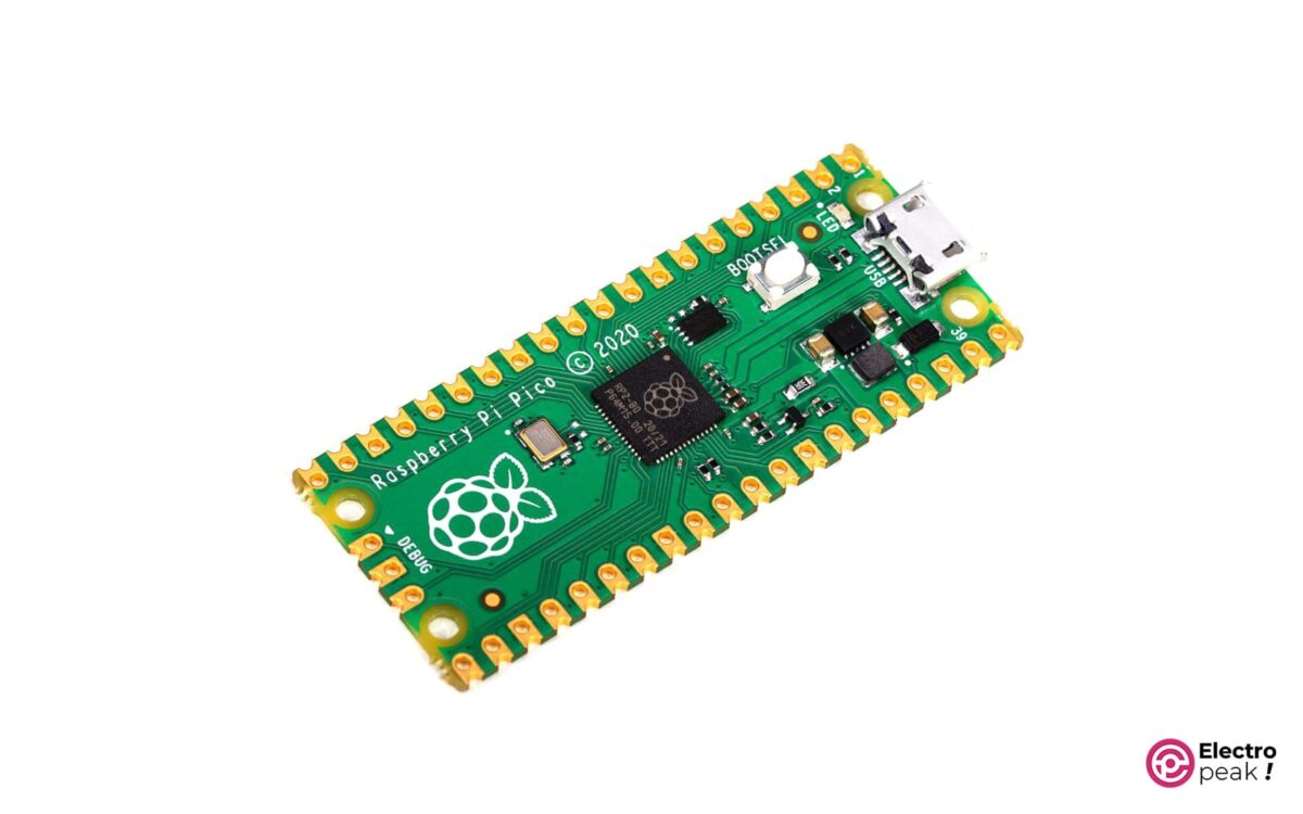
What is Raspberry Pi Pico?
Raspberry Pi Pico is a microcontroller development board designed by the Raspberry Pi Foundation. It’s equipped with the RP2040 chip, which features a dual-core Arm Cortex-M0+ processor. The board also has 26 multi-purpose GPIO pins with various functions.
One of the notable features of Raspberry Pi Pico is its low cost compared to many other microcontrollers on the market. Despite its low price, it doesn’t compromise on performance or capabilities. That’s why it’s highly popular among both beginners and experienced developers.
If you are new to Raspberry Pi Pico, you can read our guide on How to Program Raspberry Pi Pico with Arduino IDE.
In addition to everything mentioned before, the small size of this board (21×51 millimeters) is also an advantage, making it suitable for projects with limited space.
Due to the mentioned capabilities, this board has a wide range of applications, from robotics to home automation and more.
Benefits of Oscilloscope with Raspberry Pi Pico and Scoppy
The Raspberry Pi Pico oscilloscope, also known as Scoppy, provides many benefits for DIY electronics enthusiasts. Firstly, it’s cost-effective. Traditional oscilloscopes can cost hundreds or even thousands of dollars, but you can build Scoppy for less than $10. Secondly, it is open source, allowing users to customize and develop it.
Furthermore, the compact size of Scoppy makes it perfect for on-the-go projects. Whether you are working on a DIY electronics project at home, in a lab, or on the road, you can easily carry Scoppy with you. It’s so small that you can even put it in your pocket.
Additionally, Scoppy is compatible with the Android system, making it easier to work with this oscilloscope. You can use your smartphone or tablet to analyze and visualize electronic signals. This eliminates the need for additional monitors or computers, simplifies your settings, and allows you to focus on your projects. With Scoppy and an Android device, you have the power to analyze electronic signals right at your fingertips.
Android Compatibility with Scoppy
To use Scoppy on Android, you’ll need a device running Android version 5.0 (Lollipop) or higher. If you’re using a regular Raspberry Pi Pico board, your device should support the USB On-The-Go (OTG) functionality. This allows your Android device to act as a host for USB devices like Scoppy. Most modern Android devices have this capability.
In the next section, we’ll learn how to set up Scoppy on Android and familiarize ourselves with its features and functionalities.
Required Materials
Step 1: Upload the Code and Install Scoppy - Oscilloscope with Raspberry Pi Pico
To build your Oscilloscope with Raspberry Pi Pico, first step is to set up Scoppy on an Android device. Start by downloading the Scoppy app from the Google Play Store. This app acts as a bridge between your Raspberry Pi Pico board and your Android device, allowing you to view electronic signals.
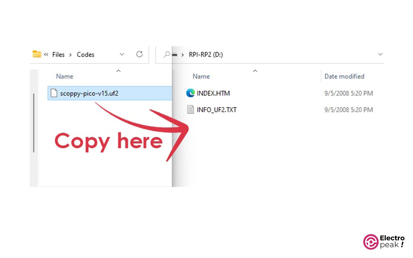
Once you have installed the Scoppy app, it’s time to program your Raspberry Pi Pico board. Just download the file from the provided link below and copy it to the memory of your Raspberry Pi Pico.
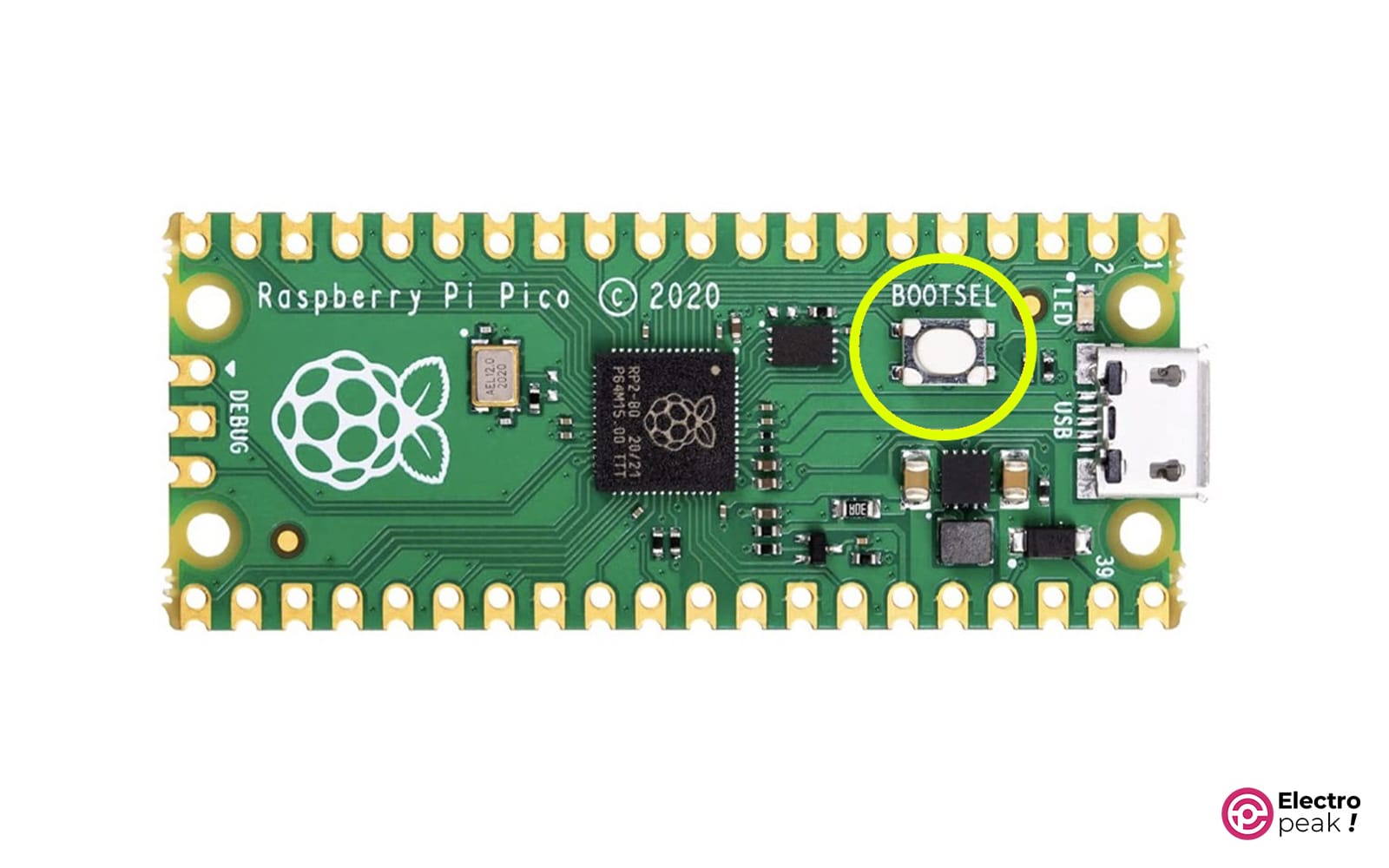
This will open a drive for you. Simply copy the downloaded file into the drive. Once the copying process is complete, the Raspberry Pi Pico will reset automatically.
Now that your Raspberry Pi Pico board is ready, let’s move on to the settings of the Scoppy app on your Android device and connect the Raspberry Pi board to it.
Here, there are two connection modes: wired and wireless.
Step 2: Connect to the Android Device - Oscilloscope with Raspberry Pi Pico
Connecting Raspberry Pi Pico via USB Cable
If you have a regular Raspberry Pi Pico, connect one side of the USB cable to the micro USB port of the Raspberry Pi Pico and the other side to the USB port of your Android device.
When you connect the Raspberry Pi Pico board to your Android device for the first time, you may need to let the app access USB devices. Simply follow the instructions on the screen to do this. Once the connection is established, you will see a notification indicating that Scoppy is connected and ready to use.
Connecting Raspberry Pi Pico W via WiFi
You can connect the firmware you installed on Pico W to your Android phone or tablet via USB or WiFi. When connecting via WiFi, you have the option to configure the Pico W as an Access Point or a Client.
You may prefer to configure your Raspberry Pi Pico W as a Client so that it can connect to your local network. Let’s see how we can do that.
The initial setup of Scoppy for configuring it as a client can be done via USB or WiFi. Our recommendation is to do this with USB. We will explain both methods.
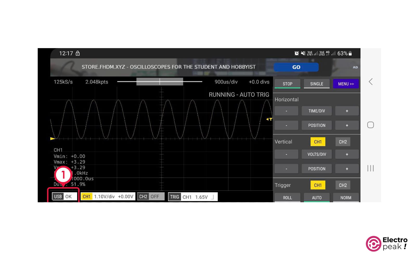
The image below shows the connection settings button in the Scoppy application.
- Initial Setup via USB
- Check the connection icon at the bottom left of the app to ensure that the connection type is set to USB. If it’s not, tap on it and select “Change connection type,” and then select the USB option.
- Connect the Raspberry Pi Pico W board to your phone/tablet using a USB cable and an OTG adapter.
- Android may ask for permission to access USB for the Scoppy app. If so, tap on Yes/OK.
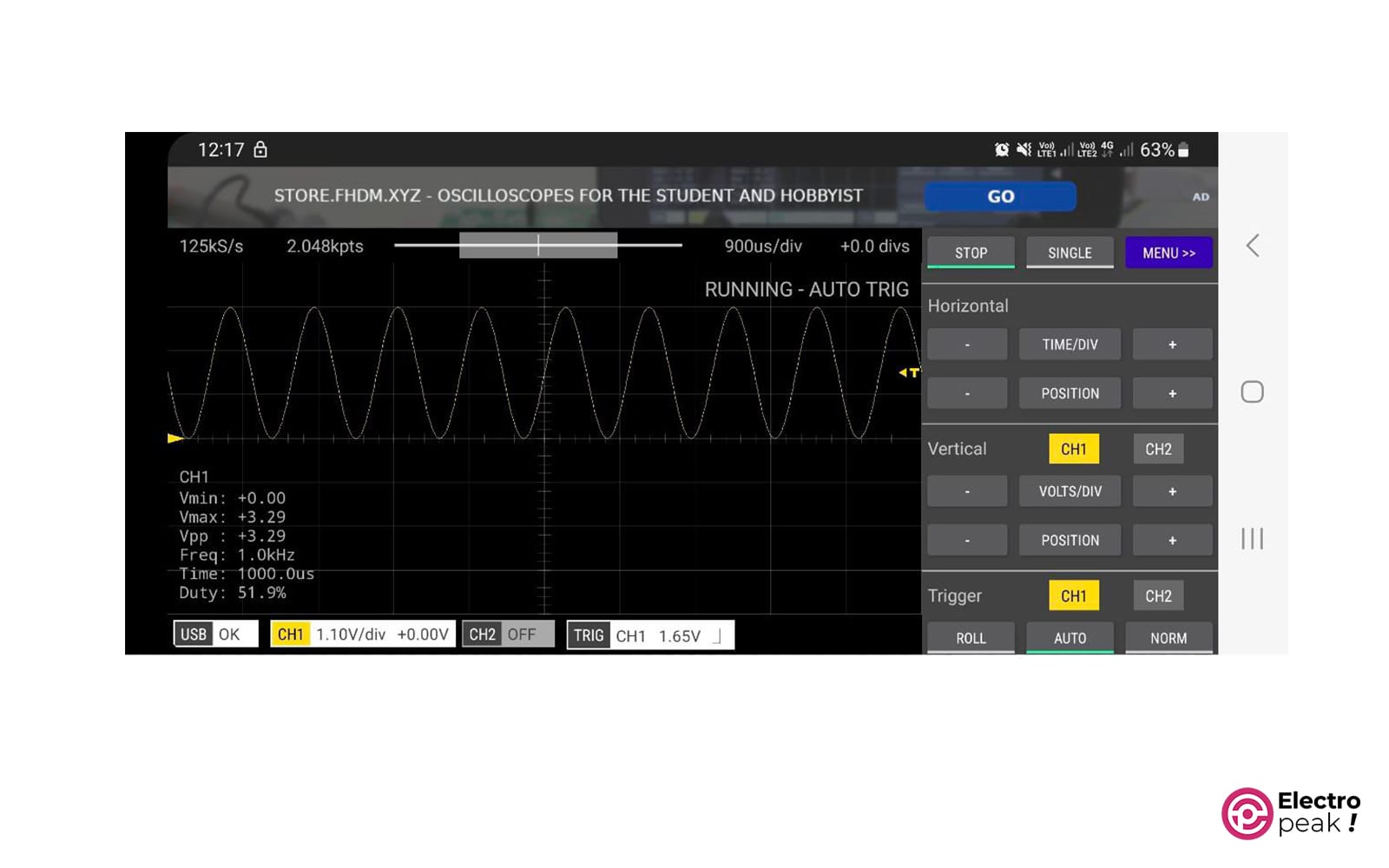
- The connection icon at the bottom left should display “USB: OK”. Please note that if the USB connection is not established within 10 seconds, the Raspberry Pi Pico W will start listening for connections via WiFi. To reconnect via USB, you need to reset the Raspberry Pi Pico W.
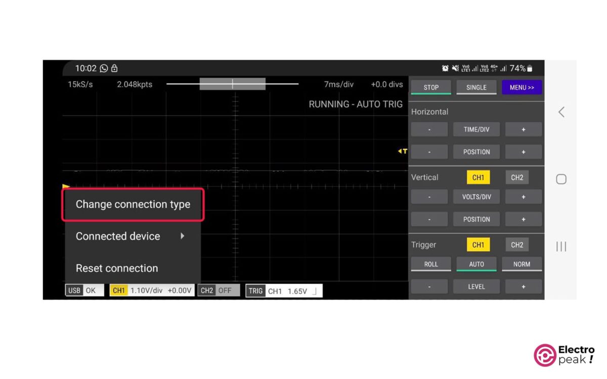
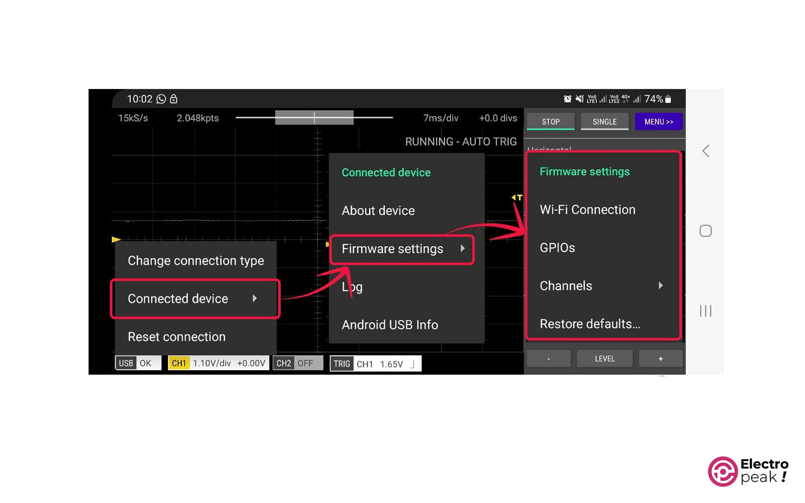
- Tap on the connection icon and select “Connected device” and then “Firmware settings” from the menu.a
- Update the Firmware settings. To do that, refer to the section “Updating Firmware settings on Raspberry Pi Pico W” provided for this step.
- Now you are ready to connect to Raspberry Pi Pico W using WiFi. Tap on the connection icon and select “Change connection type” to change the connection type to WiFi.
- Initial Setup via WiFi
- Connect the Raspberry Pi Pico W board to a 5V DC power supply.
- Wait for the status LED to blink 4 times with a 1- to 2-second interval. This indicates that the Raspberry Pi Pico W is in “Access Point” mode and waiting for Scoppy to connect via WiFi (if you power the Raspberry Pi Pico W with a computer or tablet, it may take about 10 seconds for the Raspberry Pi Pico W to be ready to accept WiFi connections).
- Go to the WiFi settings on your phone/tablet. Connect to the network starting with SCOPPY (e.g., SCOPPY-A1234BC5678DE12A). Please note that when your phone/tablet is connected to the SCOPPY network, internet access through WiFi will be disconnected.
- Go back to the Scoppy app.
- Tap on the Connection icon at the bottom left of the screen. This will display the connection settings menu.
- Tap on the “Change connection type” option and select WiFi.
- The Scoppy app will automatically connect to the Scoppy Firmware on the Raspberry Pi Pico W (the connection icon should display “WiFi OK”). You may need to tap on the RUN button to establish a connection with Scoppy.
- Tap on the connection icon again and select “Connected device” and then “Firmware settings” from the menu.
- Update the Firmware settings. For this, see the “Updating Firmware Settings on Raspberry Pi Pico W” section provided for this part.
- When the Raspberry Pi Pico is reset, your phone/tablet should automatically connect to your local network. If not, go to the Wi-Fi settings on your phone/tablet and select your local network.
- Here, the Scoppy app will connect to the Raspberry Pi Pico W. After the connection is established, the status LED on the Raspberry Pi Pico W will not blink.
- If the Raspberry Pi Pico W fails to connect to the local network, you may need to reset the Firmware settings. To do this, you have two options: copy this file to the Raspberry Pi Pico W (this will cause it to return to Access Point mode), or connect via USB.
- Turn off the board and copy the Scoppy Firmware file with the “uf2” extension onto it (go back to the first step).
How to Update Firmware Settings on Raspberry Pi Pico W
- Tap on the Connection icon at the bottom left of the screen and select “Connected device” and then “Firmware settings.”
- Select your country from the WiFi country list.
- Change the WiFi mode to Station/Client.
- Enter the SSID and password for your Access Point network.
- If you know the authentication type configured on your Access Point, select the appropriate option. Otherwise, set this section to “WPA2/WPA Mixed” mode.
- Leave the “Scoppy Access Code” section empty.
- Tap on OK.
- Reset the Raspberry Pi Pico board.
With a successful connection, you can now use this small oscilloscope.
In the next section, we will take a closer look at what Scoppy offers and how you can make the most of this powerful tool.
Step 3: Exploring the Features and Capabilities of Scoppy - Oscilloscope with Raspberry Pi Pico
It’s now time to explore the features of your Oscilloscope with Raspberry Pi Pico. Scoppy is packed with features and capabilities that make it a handy tool for DIY electronic projects. Let’s examine some key features that make Scoppy different and see how you can use them to improve your projects.
1- Signal analysis and measurement
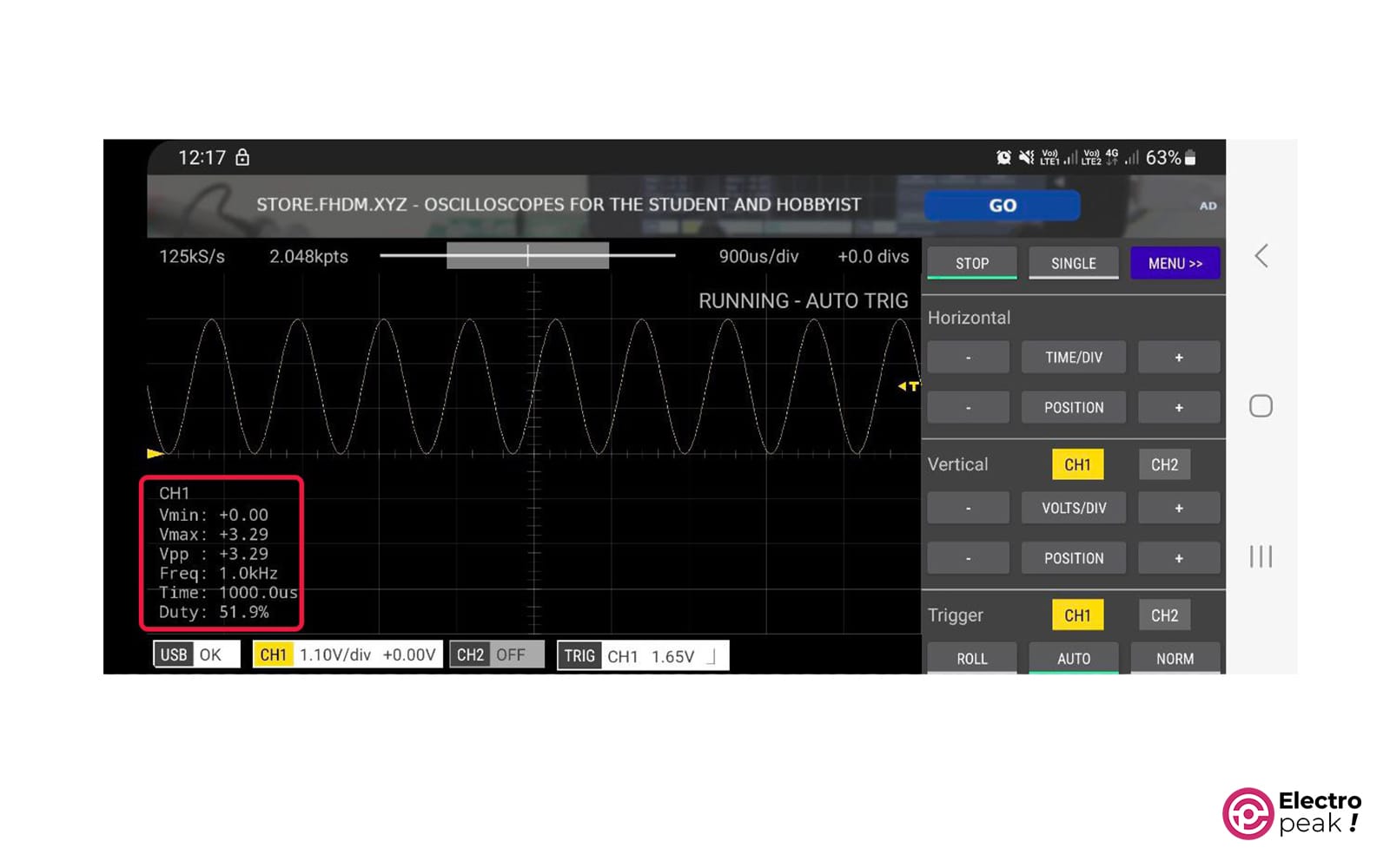
Scoppy is more than just a visual representation of a simple waveform. It provides a wide range of signal analysis and measurement capabilities. With visual controls, you can directly measure parameters such as voltage, frequency, period, and duty cycle on the measured waveform. This allows you to gather vital data for your circuit and make informed decisions based on accurate measurements.
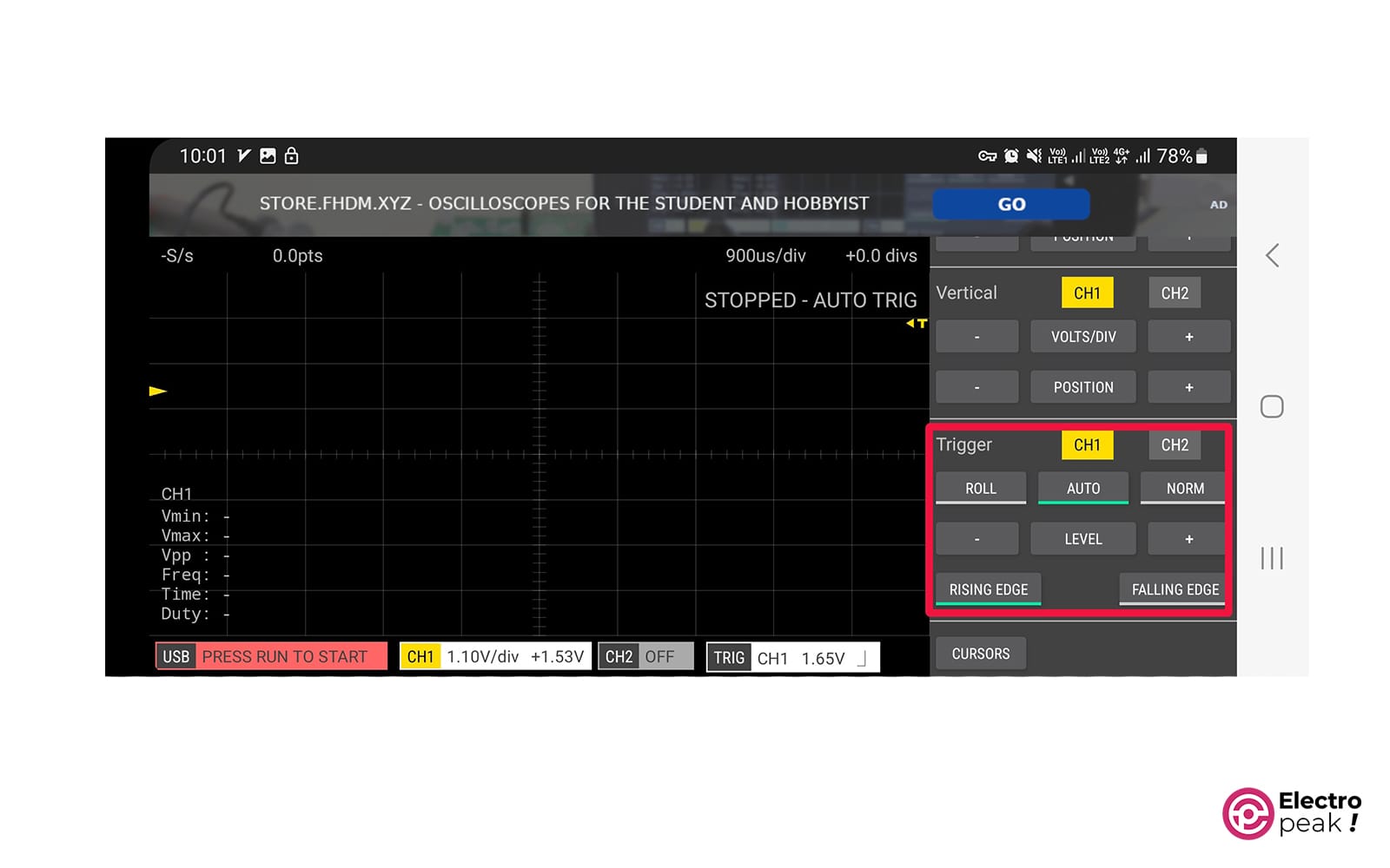
2- Trigger Settings
In Scoppy, you can use “triggers” to capture events or specific portions of a waveform. Using triggers, you can capture waveforms based on specific conditions, such as rising or falling edges. Triggers allow you to have precise control over what you see, ensuring that you won’t miss any important details.
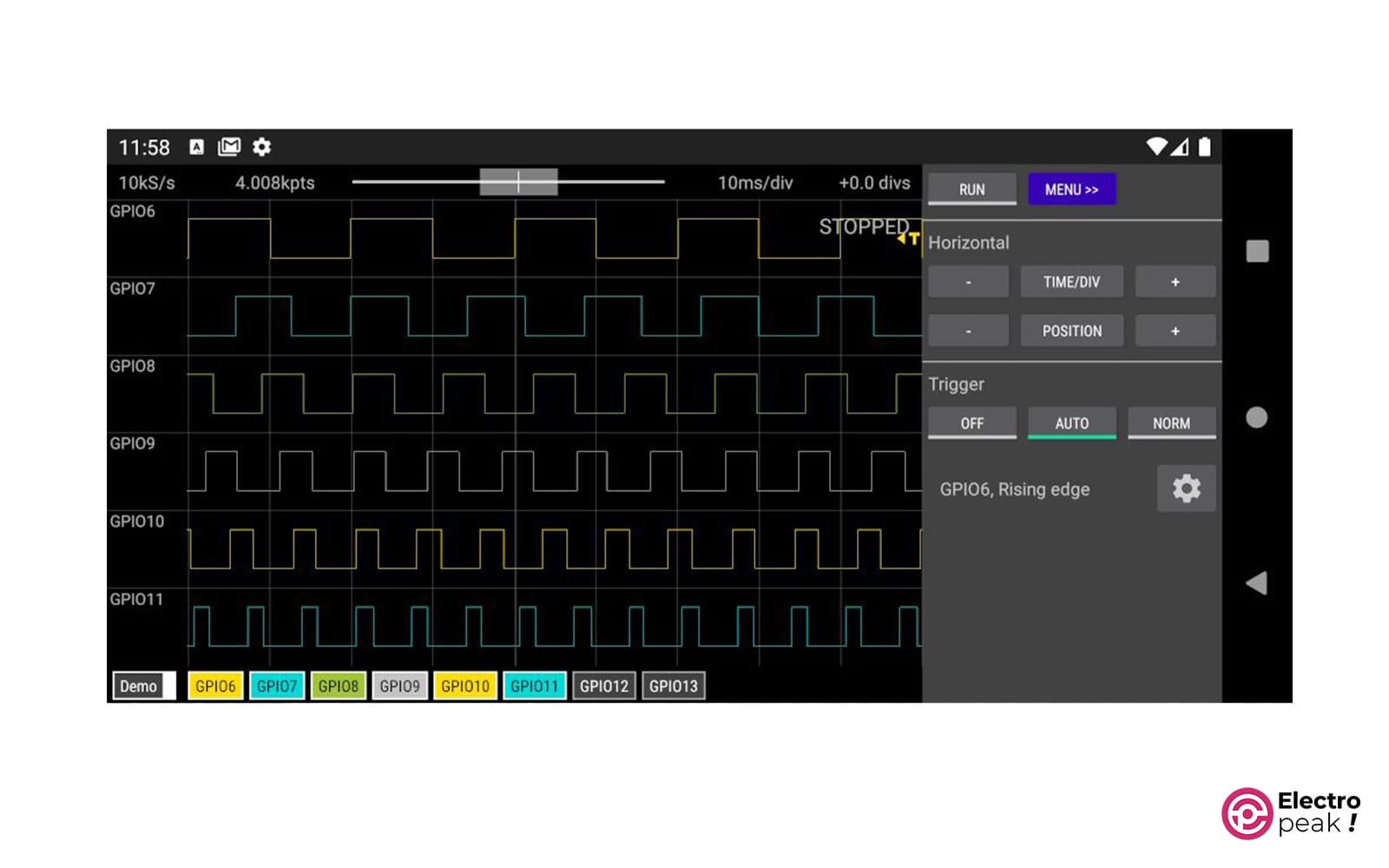
3- Logic Analyzer
Scoppy has 8 input channels for a logic analyzer. And its sampling rate is 25Ms/s.
To enter this mode, tap on the Menu button and select the “Mode” option. Then choose the “Logic analyzer” mode.
Using this mode, you can analyze the logical signals of your circuit.
However, to use more than one channel, you need to have the Premium version.
4- Signal Generator
The Scoppy application allows you to generate square and sinusoidal signals on the TEST pin. You can generate a square wave in the frequency range of 10 to 1,250,000 Hz and a 1KHz sinusoidal wave.
5- Display Mode
The oscilloscope is normally set to the Y-t display mode, which shows the signal wave within a specific time range on the screen. In addition, it has x-y, FFT (Fast Fourier Transform), and their combined mode with the Y-t mode.
With these powerful features, you can enhance your DIY electronic projects. In the next section, we will provide a step-by-step guide on how to use Scoppy on Android for your DIY electronic projects.
How to Use the Raspberry Pi Pico Oscilloscope and Scoppy App
Now that you have set up Scoppy and become familiar with its features, it’s time to use it for your electronic projects. This step-by-step guide will walk you through the process, from wiring to waveform analysis.
So let’s start using our Oscilloscope with Raspberry Pi Pico.
First, let’s take a look at the pins used on the Raspberry Pi Pico board in the image below.
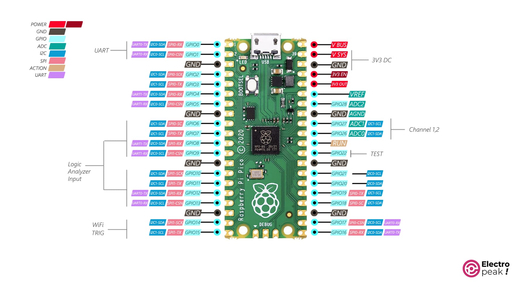
For Raspberry Pi Pico W, it’s important to connect the power pins to 3.3 volts. On the other hand, Raspberry Pi Pico doesn’t require an external power connection as it is powered via USB.
Step 1: Connect the Probes to Measurement Points
First, connect the ch.1 or ch.2 pins of your Raspberry Pi Pico (W) board to the measurement point of the signal you want to analyze. Depending on the circuit and project requirements, you may need additional components like probes or cables to ensure proper connections.
If you don’t have access to the signal source and only intend to test the oscilloscope, you can use the TEST pin. Connect this pin to either the Ch.1 or Ch.2 pin. You should be able to observe a square wave with a frequency of 1 KHz on the oscilloscope.
If the voltage at the measurement point is higher than 3.3V, you will need to use an appropriate voltage divider.
Step 2: Launch the Scoppy Application and Select the Input
After connecting with the measurement point, run the Scoppy application on your Android device. After granting the necessary permissions, select the desired input signal source on the oscilloscope screen (Ch.1 or Ch.2).
Step 3: Adjust the Settings and Trigger Conditions
To measure the waveform accurately, it is important to adjust the Trigger settings according to your project requirements. Use the visual controls in the application to adjust the voltage range, time, and trigger conditions. Try different settings until you obtain the desired waveform.
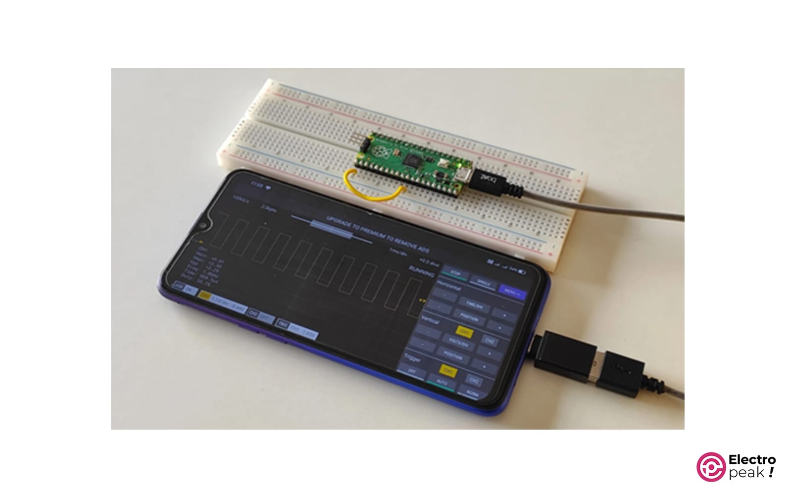
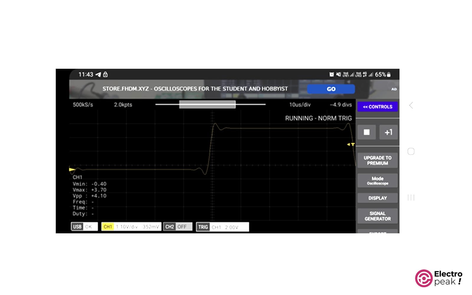
To test, we adjusted the signal generator to create a square wave with a frequency of 10 KHz and then selected the NORM option from the Trigger modes, and set the Trigger voltage to 2V. By connecting the TEST pin to the Ch.1 input and making some adjustments in TIME/DEV, you can see the following image in the output.
Step 4: Observe the Signal
After adjusting the settings, you are now ready to receive waveforms and analyze them in real-time. Now, record the waveform and observe it in the interface. Use measurement functions to gather relevant data for the waveform, such as voltage level, frequency, or duty cycle.
Step 5: Make decisions based on Analysis
You can now make informed decisions for your circuit based on the data and waveform analysis. If you identify any issues or areas for improvement, repeat your design and make the necessary adjustments. Use Scoppy to examine the changes and ensure that your circuit is functioning as expected.
Example
We generated a 500 Hz square signal with a variable duty cycle on pin 9 of the Arduino UNO using analogWrite() and connected it to probe 1 of the Raspberry Pi oscilloscope. You can watch the output in the following video.
What’s Next?
Did you enjoy building your own inexpensive and practical oscilloscope? In this tutorial, we learned how to make an oscilloscope using the Raspberry Pi Pico (w) board and the Scoppy application.
This oscilloscope is so compact that you can carry it around with you wherever you go, even in your pocket.
If you have used the W version of the Raspberry Pi Pico board, your application will be expanded due to the wireless connection. For example, you can use it for troubleshooting or analyzing the performance of a mobile robot.
If you use this board to measure voltage levels from 0 to 3.3V, you won’t need any additional components. But for higher voltages, you will need a resistive voltage divider.
You can design a development circuit for your Raspberry Pi Pico board to increase the measurement range, or you can add pins and sockets to enjoy working with your oscilloscope.
