

Overview
Power outages are one of the main problems for computers and electrical systems. Sometimes there is data and information in your system that you do not want to be deleted with a power outage. If you do not want your data and information to be lost when the power supply is disconnected, a simple way is to save your data to EEPROM memory.
In some projects, such as a 3D printer, when the system is reset, the relevant data can be stored in EEPROM memory to calibrate the equipment and initialize it. In this way, we can automatically calibrate the system when turned on.
EEPROM is the permanent memory of the system. Also, the information stored on it is not erased when the power is cut off. So, the information you need to keep in the system can be stored in EEPROM memory.
What You Will Learn
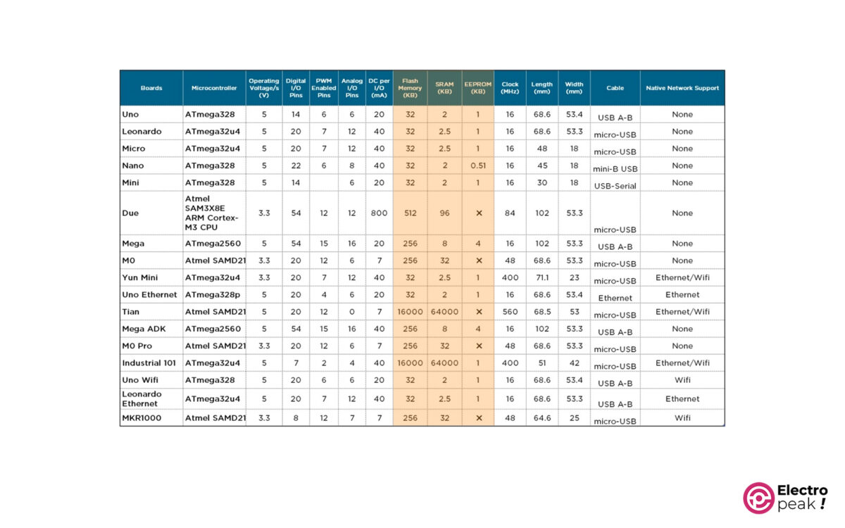
In this tutorial, we want to examine the function and role of Arduino EEPROM memory with a simple example. We are going to use an Arduino UNO board as our microcontroller. The main chip of Arduino UNO is the Atmega328P IC. This microcontroller has a 1 KB EEPROM memory.
In this tutorial, you will learn how to store and read data from Arduino EEPROM memory using the Arduino EEPROM library.
The process you will follow in this tutorial:
- What is EEPROM Memory and How it works?
- Download and install Arduino EEPROM library in Arduino IDE
- How to read/write data to Arduino EEPROM
- How to program EEPROM using Arduino in an example project.
What is EEPROM Memory?
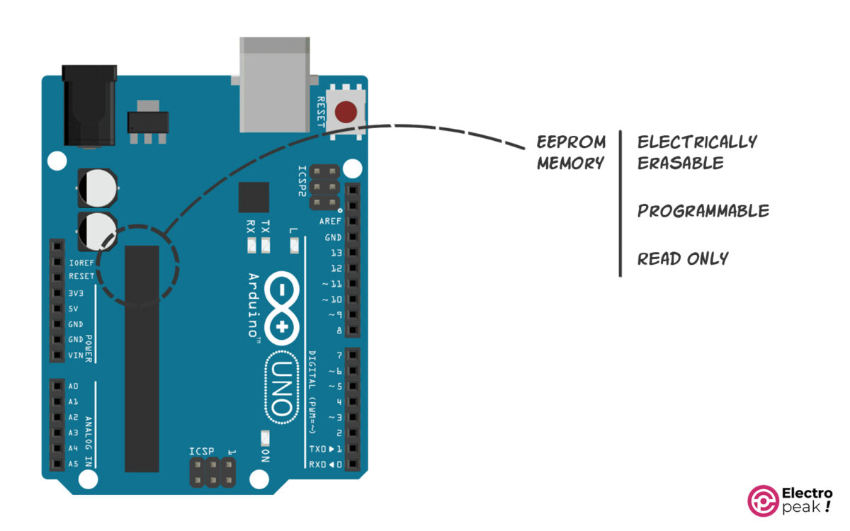
EEPROM stands for “Electrically Erasable Programmable Read-Only Memory.” This statement states that this memory is electrically programmable and is designed to be read. EEPROM is the microcontroller’s permanent memory, and you can use this small memory to store variables in bytes. That is, when the board is turned off, the data in the memory is not erased.
The most important features of EEPROM:
- The ability to read information infinitely
- Limited number of erasing and writing (around 100,000 times)
- Each EEPROM memory cell contains 1 Byte. Therefore, data with sizes 0 to 255 can be stored in them.
- The number of memory cells for the Atmega328p microcontroller is 1K byte.
Required Materials
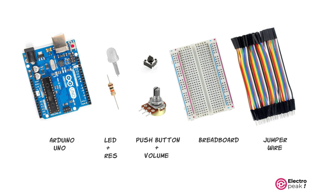
Hardware Components
Software
How to Use Arduino EEPROM
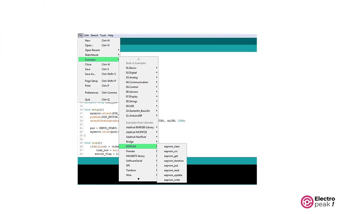
To use Arduino EEPROM we have to install Arduino EEPROM Library. This library is available on the Arduino IDE by default. You can access the EEPROM library examples via the File menu, as shown below.
Now, with an example, we will examine the most commonly used commands and functions in this library and follow the 3 steps below:
Step 1: Wiring
Using the “Update” command, we can store the desired value (0 to 255) in each of the EEPROM memory cells. The “Write” command also has a similar function. But the only advantage of the “Update” command over the “Write” command is that: before performing the write operation on the cell, it checks whether this new value is the same as the previous value stored on it. If it is the same, it will no longer perform the “write” operation. This will help extend the life of the EEPROM memory.
There is also another important command called “read” that is used to read information from the EEPROM memory address.
Now we are going to test the performance of these commands with a simple experiment.
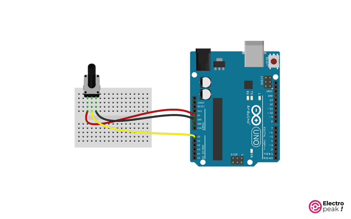
First, prepare the circuit below and connect the input pin to A0.
Step 2: َUpload Code to Read/Write Data to EEPROM
Next, we want to store the potentiometer values on the EEPROM memory cells in order. To do this, upload the following code on your Arduino:
#include <EEPROM.h>

int address = 0;
const int pot = A0;

void setup() {
 Serial.begin(9600);
}

void loop() {

 Serial.println("Ready to write to 0-20 Address of EEPROM");
 delay(3000);

 for (address = 0 ; address <= 20 ; address++) {

 int reading = analogRead(pot);
 int val = map(reading, 0, 1023, 0, 255);

 Serial.print("Address: ");
 Serial.print(address);
 Serial.print(" write: ");
 Serial.println(val);

 EEPROM.update(address, val);

 delay(500);
 }

 Serial.println();
 Serial.println("Ready to see value of 0-20 Address of EEPROM");
 delay(2000);

 for (address = 0 ; address <= 20 ; address++) {

 int data = EEPROM.read(address);

 Serial.print("Address: ");
 Serial.print(address);
 Serial.print(" read: ");
 Serial.println(data);
 delay(500);
 }
 Serial.println();
}
In this program, we intend to save the desired values between 0 and 255 in the cells 0 to 20 of the EEPROM memory with the “EEPROM.update” command, and then we read the values stored on the memory with the “EEPROM.read” command. When writing, the potentiometer data is stored at 0 to 20 EEPROM addresses, each in half a second.
Step 3: Output
After uploading the code above, open the Arduino Serial Monitor to view the output. When the monitor serial is opened, the phrase “Ready to write to 0-20 Address of EEPROM” appears. Three seconds later, the data on pin A0 will be stored at addresses 0 to 20 with a half-second interval. You can change the value stored by turning the potentiometer.
Then, after a 2-second pause, the data written at the 0 to 20 addresses is read and displayed on the Serial Monitor. As expected, the data read from addresses 0 to 20 correspond to the data written on it.
The following video further supports the above description:
Example: Remember Last LED State in EEPROM
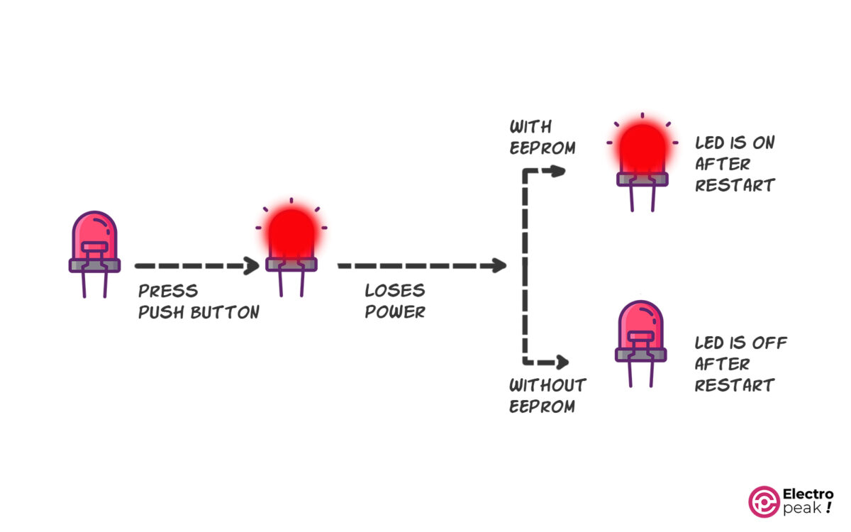
Now you have learned how to program EEPROM using Arduino and it’s time to put it into action with a practical example. In this example, we are going to evaluate the performance of EEPROM. We turn an LED on and off with a push button. The purpose is to store the LED status on the EEPROM memory so that when the system is reset or the circuit supply is cut off, the LED status would be the same as before, i.e. if the LED is on when the power goes out, the LED will be immediately on when connected.
This is the opposite of normal mode, in which, when the system is reset, the LED status returns to its default value.
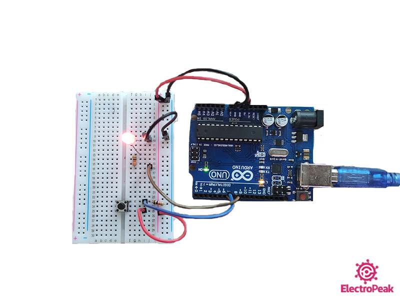
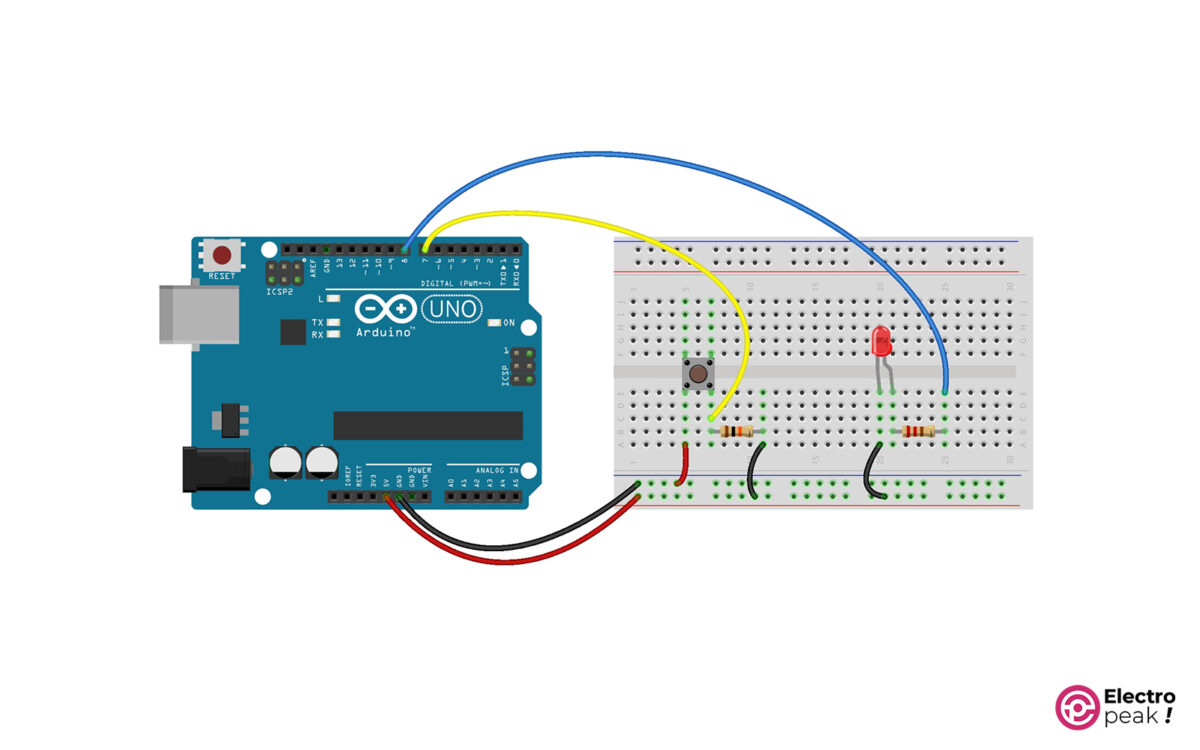
Step 1: Wiring
First, we prepare the circuit as follows:
Step 2: Code
Upload the following code to your Arduino Board:
/*

Made on 22 Aug 2021
By Amirmohammad Shojaei
Home
based on randomnerdtutorials.com example

*/

#include

const int buttonPin = 7; // pushbutton pin
const int ledPin = 8; // LED pin

int ledState; // variable to hold the led state
int buttonState; // the current reading from the input pin
int lastButtonState = LOW; // the previous reading from the input pin

// the following variables are long's because the time, measured in miliseconds,
// will quickly become a bigger number than can be stored in an int.

long lastDebounceTime = 0; // the last time the output pin was toggled
long debounceDelay = 50; // the debounce time; increase if the output flickers

void setup() {

// set input and output
pinMode(buttonPin, INPUT);
pinMode(ledPin, OUTPUT);

//check stored LED state on EEPROM using function defined at the end of the code
checkLedState();

}

void loop() {

// read the state of the switch into a local variable
int reading = digitalRead(buttonPin);

if(reading != lastButtonState) {

// reset the debouncing timer
lastDebounceTime = millis();

}

if((millis() - lastDebounceTime) > debounceDelay) {

// whatever the reading is at, it's been there for longer
// than the debounce delay, so take it as the actual current state:
// if the button state has changed:

if(reading != buttonState) {
buttonState = reading;

// only toggle the LED if the new button state is HIGH
if(buttonState == HIGH) {
ledState = !ledState;

}
}
}

// set the LED state
digitalWrite(ledPin, ledState);

// save the current LED state in the EEPROM
EEPROM.update(0, ledState);

// save the reading. Next time through the loop,
// it'll be the lastButtonState

lastButtonState = reading;
}

// Prints and upates the LED state
// when the Arduino board restarts or powers up

void checkLedState() {
ledState = EEPROM.read(0);
if(ledState == 1) {
digitalWrite(ledPin, HIGH);
}

if(ledState == 0) {
digitalWrite(ledPin, LOW);

}
Here are a few tips about the code above:
- The EEPROM library is included.
- The code is based on the Arduino “Debounce” example.
- In this program, after each time a switch is pressed, the new LED status is stored at address 0 of the EEPROM memory.
- Now, a function called “checkLedState()” is defined. This function is used in the Setup() loop and runs after each time the Arduino is turned on. Executing this function causes the LED status to match exactly what is stored at address 0 of the EEPROM memory.
Step 3: Output
The output is as follows:
As you can see:
- If the LED is on before the reset, it remains on after the reset.
- If the LED is off before the reset, it remains off after the reset
What’s Next?
After completing this tutorial, you can do the following projects as the next step:
- Use the AT24LC256 IC as an external EEPROM
- Learn the functions of other types of memory
