

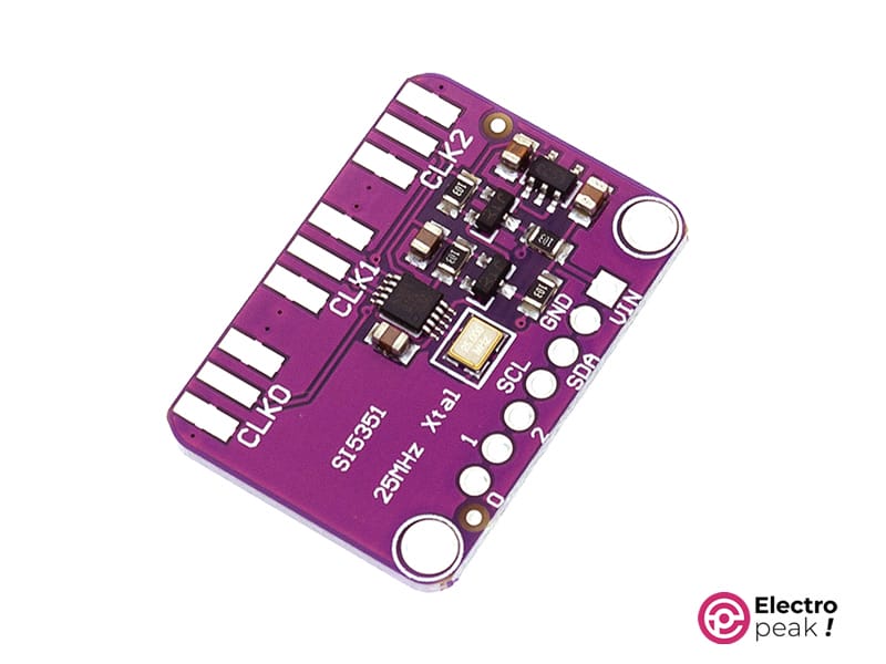
SI5351 Signal Square Wave Generator Features
The SI5351 Signal Square Wave Generator Module is your go-to tool for crafting precise and customizable square wave signals effortlessly. This nifty module is designed to make generating signals a breeze, offering a simple and user-friendly solution for hobbyists and electronics enthusiasts. What sets the SI5351 apart is its ability to produce highly accurate square wave signals across a wide frequency range, making it perfect for a variety of applications, from tinkering with amateur radio projects to creating DIY electronic instruments. With its compact design and straightforward interface, this module is suitable for both beginners and experienced makers. Elevate your projects with the SI5351, a versatile and reliable signal generator that brings simplicity and precision to your electronic experiments.
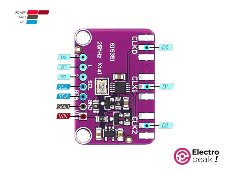
SI5351 Signal Square Wave Generator Pinout
The SI5351 Signal Square Wave Generator has 7 pins:
- VIN: Power supply input for the SI5351 module (5V).
- GND: Ground reference, ensuring a stable electrical connection.
- SCL: Serial Clock Line for communication with microcontrollers.
- SDA: Serial Data Line for configuring the module’s settings.
- D0-D2: Output pins for customizable square wave signals.
You can see the pinout of this module in the image below.
Required Material
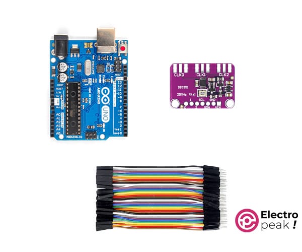
Hardware Components
Interfacing SI5351 Signal Square Wave Generator with Arduino
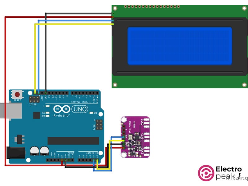
Step 1: Circuit
The following circuit shows how you should connect Arduino to SI5351 Signal Square Wave Generator. Connect wires accordingly.
You don’t have to connect the display if you don’t need it.
Step 2: Installing Library
Step 3: Code
To interface the board without a display, upload the following code to your Arduino.
/*
Create on January 27, 2024
Create by MohammedDamirchi base of https://github.com/adafruit/Adafruit_Si5351_Library
<blockquote class="wp-embedded-content" data-secret="NKl1sgbB6f"><a href="https://electropeak.com/learn/">Home</a></blockquote><iframe class="wp-embedded-content" sandbox="allow-scripts" security="restricted" style="position: absolute; clip: rect(1px, 1px, 1px, 1px);" title="“Home” — Electropeak" src="https://electropeak.com/learn/embed/#?secret=eb2yOuAD2I#?secret=NKl1sgbB6f" data-secret="NKl1sgbB6f" width="600" height="338" frameborder="0" marginwidth="0" marginheight="0" scrolling="no"></iframe>
*/
#include <Arduino.h>
#include <SPI.h>
#include <Adafruit_SI5351.h>
Adafruit_SI5351 clockgen = Adafruit_SI5351();
void setup()
{
Serial.begin(115200);
while (!Serial)
;
Serial.println("Si5351 Clockgen Test");
/* Initialise the sensor */
if (clockgen.begin() != ERROR_NONE)
{
/* There was a problem detecting the IC ... check your connections */
Serial.print("Ooops, no Si5351 detected ... Check your wiring or I2C ADDR!");
while (1)
;
}
Serial.println("OK!");
/* INTEGER ONLY MODE --> most accurate output */
/* Setup PLLA to integer only mode @ 900MHz (must be 600..900MHz) */
/* Set Multisynth 0 to 112.5MHz using integer only mode (div by 4/6/8) */
/* 25MHz * 36 = 900 MHz, then 900 MHz / 8 = 112.5 MHz */
Serial.println("Set PLLA to 900MHz");
clockgen.setupPLLInt(SI5351_PLL_A, 36);
Serial.println("Set Output #0 to 112.5MHz");
clockgen.setupMultisynthInt(0, SI5351_PLL_A, SI5351_MULTISYNTH_DIV_8);
/* FRACTIONAL MODE --> More flexible but introduce clock jitter */
/* Setup PLLB to fractional mode @616.66667MHz (XTAL * 24 + 2/3) */
/* Setup Multisynth 1 to 13.55311MHz (PLLB/45.5) */
clockgen.setupPLL(SI5351_PLL_B, 24, 2, 3);
Serial.println("Set Output #1 to 13.553115MHz");
clockgen.setupMultisynth(1, SI5351_PLL_B, 45, 1, 2);
/* Multisynth 2 is not yet used and won't be enabled, but can be */
/* Use PLLB @ 616.66667MHz, then divide by 900 -> 685.185 KHz */
/* then divide by 64 for 10.706 KHz */
/* configured using either PLL in either integer or fractional mode */
Serial.println("Set Output #2 to 10.706 KHz");
clockgen.setupMultisynth(2, SI5351_PLL_B, 900, 0, 1);
clockgen.setupRdiv(2, SI5351_R_DIV_64);
/* Enable the clocks */
clockgen.enableOutputs(true);
}
void loop()
{
}
After uploading the code, you can have the desired frequency on the output pins.
If you need help running the display, you can refer to the following link.
To interface the board with a display, upload the following code to your Arduino.
Also, download the myLCD file and put it into your project folder

/*
Create on January 27, 2024
Create by MohammedDamirchi base of https://github.com/adafruit/Adafruit_Si5351_Library
<blockquote class="wp-embedded-content" data-secret="NKl1sgbB6f"><a href="https://electropeak.com/learn/">Home</a></blockquote><iframe class="wp-embedded-content" sandbox="allow-scripts" security="restricted" style="position: absolute; clip: rect(1px, 1px, 1px, 1px);" title="“Home” — Electropeak" src="https://electropeak.com/learn/embed/#?secret=eb2yOuAD2I#?secret=NKl1sgbB6f" data-secret="NKl1sgbB6f" width="600" height="338" frameborder="0" marginwidth="0" marginheight="0" scrolling="no"></iframe>
*/
#include <Arduino.h>
#include <SPI.h>
#include <Adafruit_SI5351.h>
#include <myLCD.h>
Adafruit_SI5351 clockgen = Adafruit_SI5351();
void setup()
{
Serial.begin(115200);
beginLCD("Adafruit Si5351");
while (!Serial)
;
Serial.println("Si5351 Clockgen Test");
/* Initialise the sensor */
if (clockgen.begin() != ERROR_NONE)
{
/* There was a problem detecting the IC ... check your connections */
Serial.print("Ooops, no Si5351 detected ... Check your wiring or I2C ADDR!");
fail();
while (1)
;
}
Serial.println("OK!");
success();
printLCD("Si5351 Example", 0, true);
printLCD("#0 to 112.5MHz", 1);
printLCD("#1 to 13.553115MHz", 2);
printLCD("#2 to 10.706 KHz", 3);
/* INTEGER ONLY MODE --> most accurate output */
/* Setup PLLA to integer only mode @ 900MHz (must be 600..900MHz) */
/* Set Multisynth 0 to 112.5MHz using integer only mode (div by 4/6/8) */
/* 25MHz * 36 = 900 MHz, then 900 MHz / 8 = 112.5 MHz */
Serial.println("Set PLLA to 900MHz");
clockgen.setupPLLInt(SI5351_PLL_A, 36);
Serial.println("Set Output #0 to 112.5MHz");
clockgen.setupMultisynthInt(0, SI5351_PLL_A, SI5351_MULTISYNTH_DIV_8);
/* FRACTIONAL MODE --> More flexible but introduce clock jitter */
/* Setup PLLB to fractional mode @616.66667MHz (XTAL * 24 + 2/3) */
/* Setup Multisynth 1 to 13.55311MHz (PLLB/45.5) */
clockgen.setupPLL(SI5351_PLL_B, 24, 2, 3);
Serial.println("Set Output #1 to 13.553115MHz");
clockgen.setupMultisynth(1, SI5351_PLL_B, 45, 1, 2);
/* Multisynth 2 is not yet used and won't be enabled, but can be */
/* Use PLLB @ 616.66667MHz, then divide by 900 -> 685.185 KHz */
/* then divide by 64 for 10.706 KHz */
/* configured using either PLL in either integer or fractional mode */
Serial.println("Set Output #2 to 10.706 KHz");
clockgen.setupMultisynth(2, SI5351_PLL_B, 900, 0, 1);
clockgen.setupRdiv(2, SI5351_R_DIV_64);
/* Enable the clocks */
clockgen.enableOutputs(true);
}
void loop()
{
}
After uploading the code, you can view the module output on your oscilloscope as shown in the video below.
