
SN74HC164D 8bit Shift Register Module Features
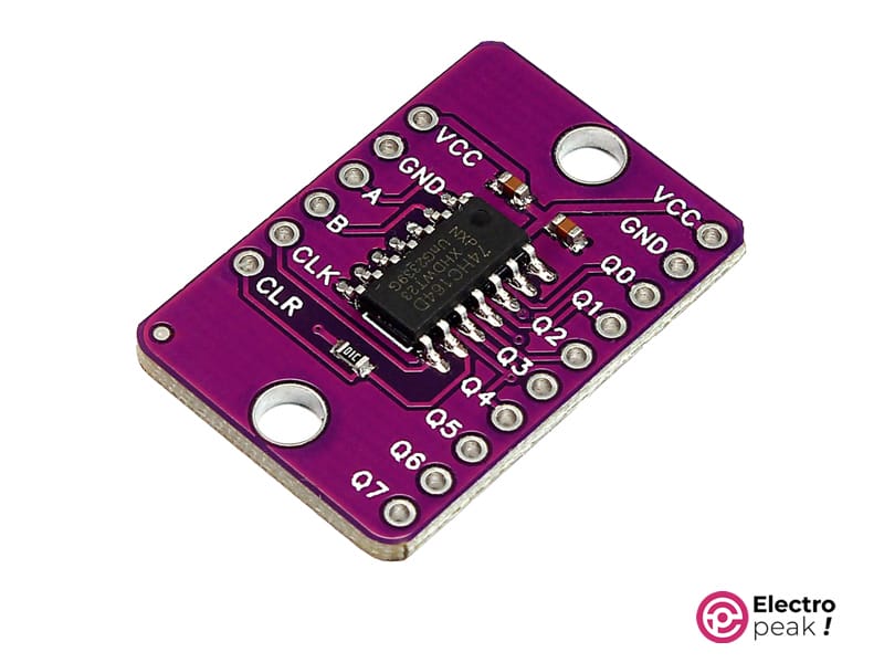
The SN74HC164D 8-bit Shift Register Module is a powerful and user-friendly electronic component widely used in digital circuitry. This module serves as a convenient way to expand the number of output pins on microcontrollers, making it an essential tool for electronics enthusiasts and engineers. Its key property lies in its ability to efficiently control multiple outputs with minimal input pins, offering flexibility in managing various components within a circuit. The shift register’s straightforward operation involves serially shifting data into the module, allowing for parallel output control. This simplicity makes it an excellent choice for projects where space and pin count are crucial considerations. With compatibility across various microcontrollers, such as Arduino and Raspberry Pi, the SN74HC164D simplifies the process of cascading multiple modules for even greater expansion. Its versatility, ease of use, and compatibility make it a go-to solution for hobbyists and professionals alike, enhancing the efficiency and functionality of digital circuits.
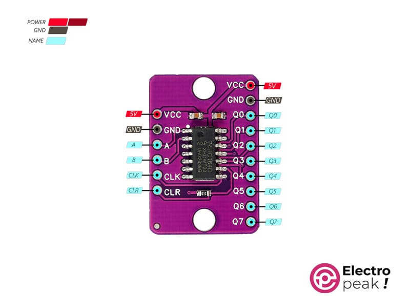
SN74HC164D Module Pinout
The SN74HC164D 8bit Shift Register Module has 13 pins:
- VCC (5V): Power supply input.
- GND: Ground reference for the module.
- A: Input A for Serial input for introducing data into the shift register
- B: Input B serves as the Input Enable.
- CLK: Clock input for synchronizing the shifting of data within the register.
- CLR (MR): Master Reset, allowing a complete reset of the shift register.
- Q1: Output for the first bit, forming the initial data output.
- Q2: Output for the second bit, crucial for serial data flow.
- Q3: Output for the third bit in the shift register sequence.
- Q4: Output for the fourth bit, playing a role in the cascading of data.
- Q5: Output for the fifth bit, facilitating sequential data transfer.
- Q6: Output for the sixth bit, contributing to data output.
- Q7: Output for the seventh bit in the shift register, the last in the series.
You can see the pinout of this module in the image below.
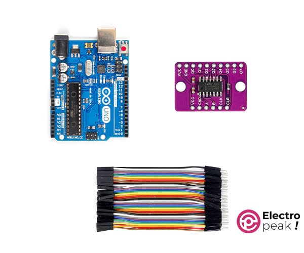
Required Material
Interfacing SN74HC164D Shift Register Module with Arduino
Step 1: Circuit
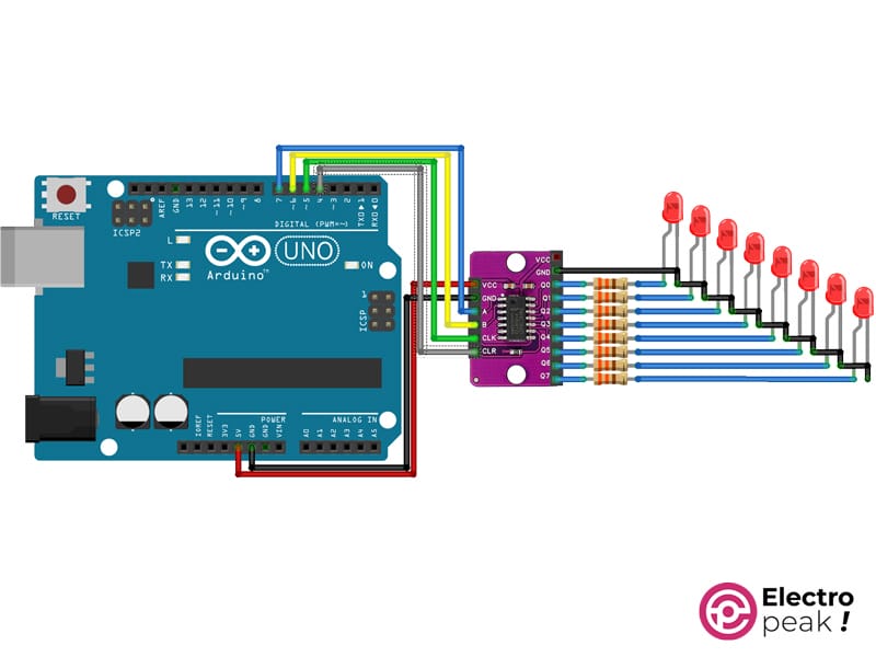
The following circuit shows how you should connect ESP32 to this module. Connect wires accordingly.
In this circuit, we’ve employed LEDs for a clearer illustration of how this module operates. However, feel free to utilize the output of this module in any circuit that requires its functionality.
Step 2: Installing Library
Install the library below on your Arduino IDE.
Step 3: Code
Upload the following code to your Arduino.
/*
Create on January 09, 2024
Create by MohammedDamirchi
<blockquote class="wp-embedded-content" data-secret="xWqlVIFj56"><a href="https://electropeak.com/learn/">Home</a></blockquote><iframe class="wp-embedded-content" sandbox="allow-scripts" security="restricted" style="position: absolute; clip: rect(1px, 1px, 1px, 1px);" title="“Home” — Electropeak" src="https://electropeak.com/learn/embed/#?secret=chWx7Fluqb#?secret=xWqlVIFj56" data-secret="xWqlVIFj56" width="600" height="338" frameborder="0" marginwidth="0" marginheight="0" scrolling="no"></iframe>
*/
#include <Arduino.h>
#include <SN74HC164D.h>
SN74HC164D xx164;
void setup()
{
Serial.begin(9600);
Serial.println("test");
xx164.begin(7, 6, 5, 4);
xx164.rainbow();
}
void loop()
{
if (Serial.available())
xx164.write(Serial.read() - 48, MSBFIRST);
}
After uploading, the LEDs will undergo changes for a brief period. Following this, you can utilize the Serial Monitor to transmit numbers ranging from 0 to 9, displaying the sent number in binary format on the LEDs.
