
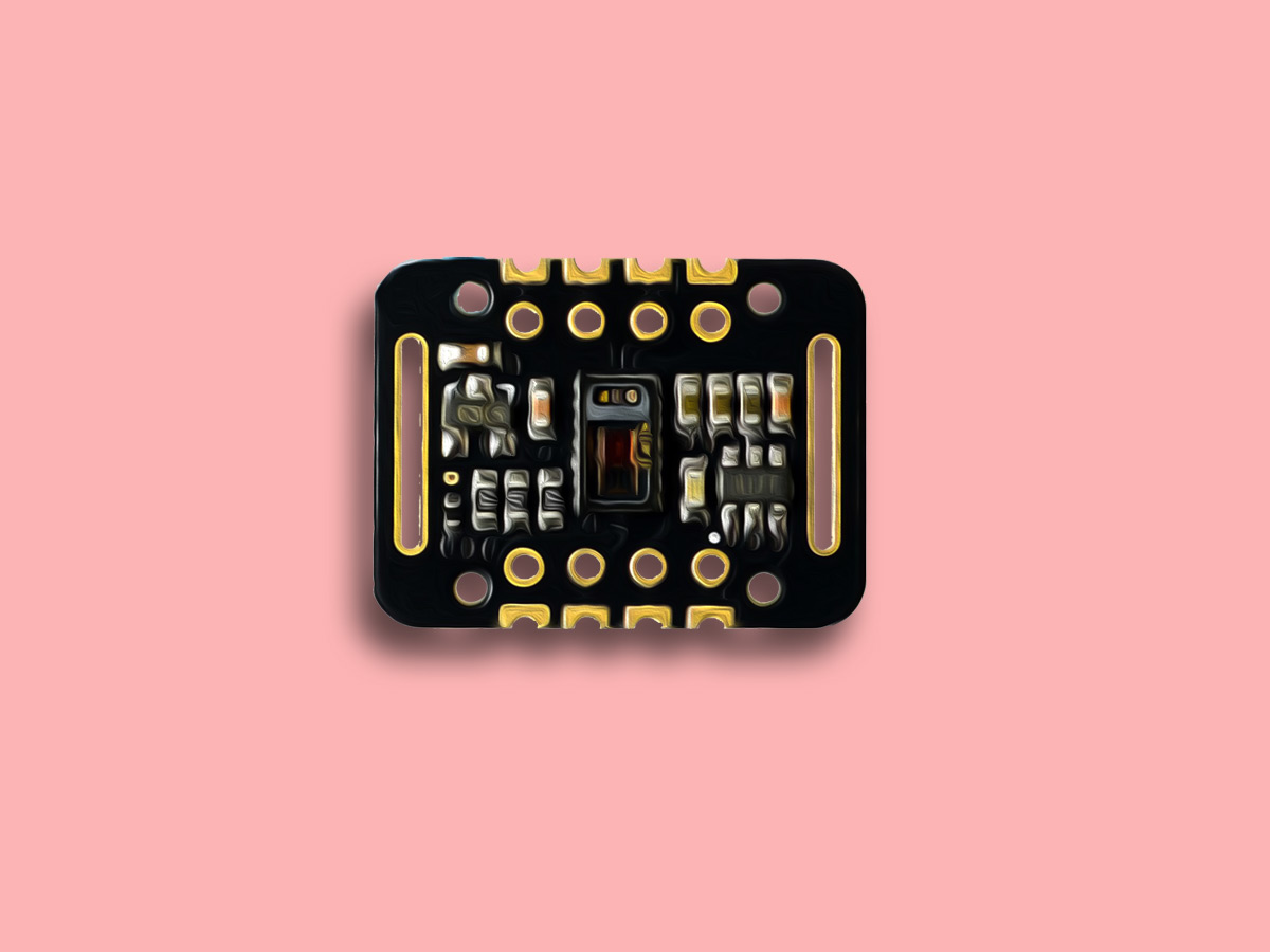
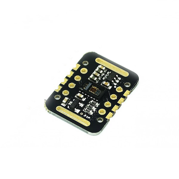
MAX30102 Heart Rate Module Features
MAX30102 sensor is used to detect blood oxygen and heart rate. First, infrared radiation is sent and reflected by hitting the finger, and then the amount of oxygen in the blood is determined by measuring the wave amplitude. Heart rate is also obtained by analyzing the time series response of this radiation.
The MAX30102 is an integrated module compatible with the Arduino and STM32. It integrates a red LED with an infrared LED, a photoelectric detector, an optical device, and a low noise electronic circuit for ambient light suppression. Heart rate and blood oxygen data are also transmitted to the Arduino or other microcontrollers via I2C communication.
You can download the datasheet of this module here.
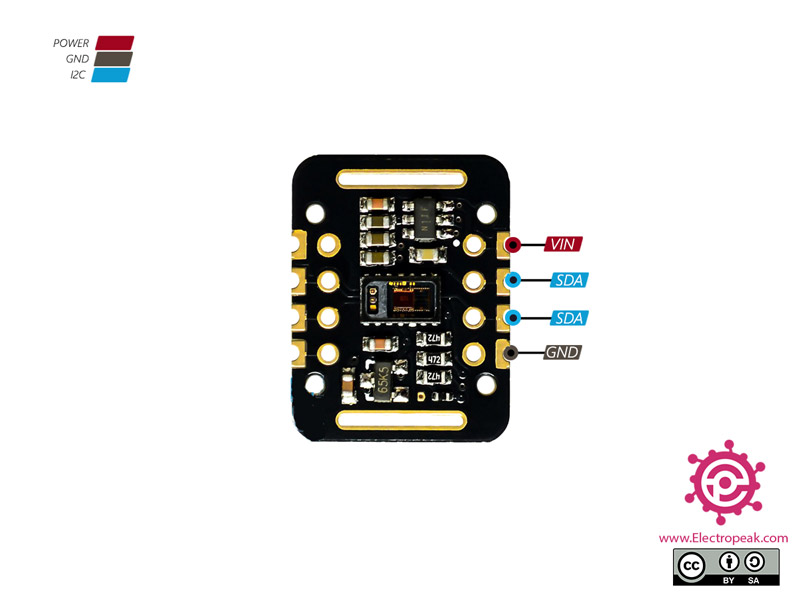
MAX30102 Heart Rate Module Pinout
This sensor has 8 pins. 4 pins are more useful:
- VCC: Module power supply – 3 to 5 V
- GND: Ground
- SCL: I2C clock bus
- SDA: I2C data bus
You can see pinout of this module in the image below.
Required Materials
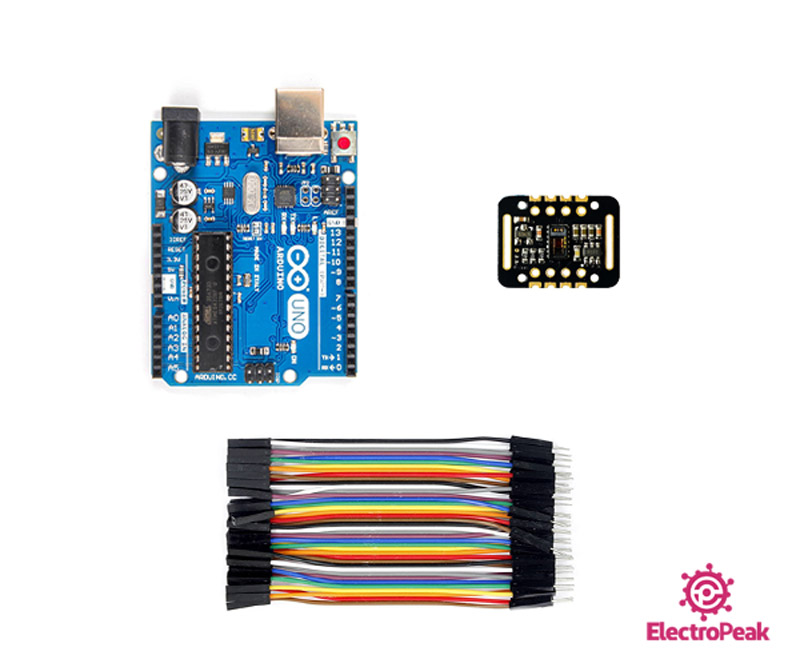
Hardware Components
Software Apps
Interfacing MAX30102 Sensor with Arduino
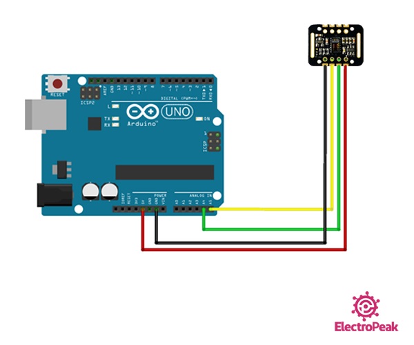
Step 1: Circuit
The following circuit shows how you should connect Arduino to MAX30102 module. Connect wires accordingly.
Note
You can use a bread board and pin header to connect module to interface wires, or you can solder pin header to module.
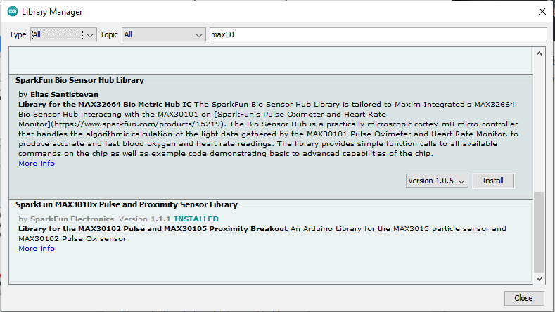
Step 2: Installing Library
Go to Library manager and search Max30, then install SparkFun Max301x.
Tip
If you need more help with installing a library on Arduino, read this tutorial: How to Install an Arduino Library
Step 3: Code for Heart Rate Detection
Upload the following code to your Arduino. This code displays your heart rate graphically in the serial monitor.
/*
MAX30102- Heart Rate Pulse Detection-Module
Home<iframe class="wp-embedded-content" sandbox="allow-scripts" security="restricted" style="position: absolute; clip: rect(1px, 1px, 1px, 1px);" title="“Home” — Electropeak" src="https://electropeak.com/learn/embed/#?secret=TxwP1tJuq2" data-secret="TxwP1tJuq2" width="600" height="338" frameborder="0" marginwidth="0" marginheight="0" scrolling="no"></iframe>
Based on Arduino Library Example
*/
#include <Wire.h>
#include "MAX30105.h"
MAX30105 particleSensor;
void setup()
{
Serial.begin(115200);
Serial.println("Initializing...");
// Initialize sensor
if (!particleSensor.begin(Wire, I2C_SPEED_STANDARD)) //Use default I2C port, 400kHz speed
{
Serial.println("MAX30105 was not found. Please check wiring/power. ");
while (1);
}
Serial.println("connected");
//Setup to sense a nice looking saw tooth on the plotter
byte ledBrightness = 0x1F; //Options: 0=Off to 255=50mA
byte sampleAverage = 8; //Options: 1, 2, 4, 8, 16, 32
byte ledMode = 3; //Options: 1 = Red only, 2 = Red + IR, 3 = Red + IR + Green
int sampleRate = 100; //Options: 50, 100, 200, 400, 800, 1000, 1600, 3200
int pulseWidth = 411; //Options: 69, 118, 215, 411
int adcRange = 4096; //Options: 2048, 4096, 8192, 16384
particleSensor.setup(ledBrightness, sampleAverage, ledMode, sampleRate, pulseWidth, adcRange); //Configure sensor with these settings
//Arduino plotter auto-scales annoyingly. To get around this, pre-populate
//the plotter with 500 of an average reading from the sensor
//Take an average of IR readings at power up
const byte avgAmount = 64;
long baseValue = 0;
for (byte x = 0 ; x < avgAmount ; x++)
{
baseValue += particleSensor.getIR(); //Read the IR value
}
baseValue /= avgAmount;
//Pre-populate the plotter so that the Y scale is close to IR values
for (int x = 0 ; x < 500 ; x++)
Serial.println(baseValue);
}
void loop()
{
Serial.println(particleSensor.getIR()); //Send raw data to plotter
}
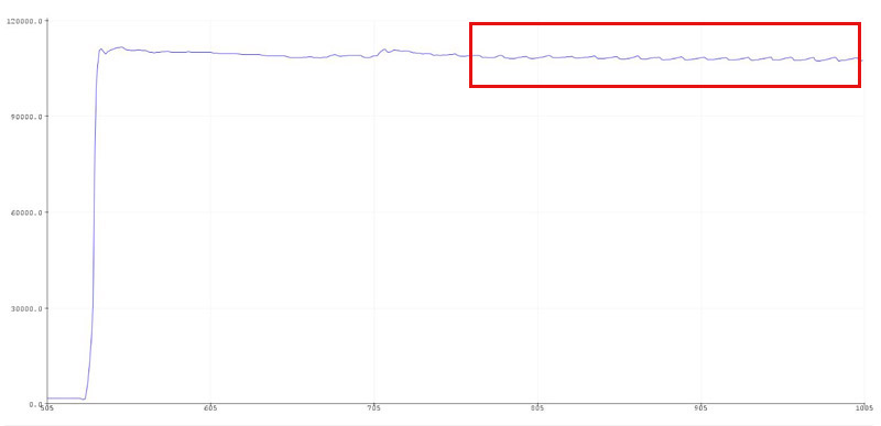
In the first part, you have to add related library to program. Next, in the setup loop, the data transfer rate is 115,200. You should set this number in the Serial plotter as well. Sampling is done at a 400 kHz frequency.
Finally, the results appear in the Serial Plotter as follows. As you can see the heart rate fluctuates:
Step 4: Code for Blood Oxygen detection
Upload the following code to your Arduino. This code displays your blood oxygen in the serial monitor.
    /*
  MAX30102- Blood Oxyge -Module
  Home

  Based on Arduino Library Example
*/


#include <Wire.h>
#include "MAX30105.h"
#include "spo2_algorithm.h"

MAX30105 particleSensor;

#define MAX_BRIGHTNESS 255

#if defined(__AVR_ATmega328P__) || defined(__AVR_ATmega168__)
//Arduino Uno doesn't have enough SRAM to store 100 samples of IR led data and red led data in 32-bit format
//To solve this problem, 16-bit MSB of the sampled data will be truncated. Samples become 16-bit data.
uint16_t irBuffer[100]; //infrared LED sensor data
uint16_t redBuffer[100];  //red LED sensor data
#else
uint32_t irBuffer[100]; //infrared LED sensor data
uint32_t redBuffer[100];  //red LED sensor data
#endif

int32_t bufferLength; //data length
int32_t spo2; //SPO2 value
int8_t validSPO2; //indicator to show if the SPO2 calculation is valid
int32_t heartRate; //heart rate value
int8_t validHeartRate; //indicator to show if the heart rate calculation is valid

byte pulseLED = 11; //Must be on PWM pin
byte readLED = 13; //Blinks with each data read

void setup()
{
  Serial.begin(115200); // initialize serial communication at 115200 bits per second:

  pinMode(pulseLED, OUTPUT);
  pinMode(readLED, OUTPUT);

  // Initialize sensor
  if (!particleSensor.begin(Wire, I2C_SPEED_FAST)) //Use default I2C port, 400kHz speed
  {
    Serial.println(F("MAX30105 was not found. Please check wiring/power."));
    while (1);
  }

  Serial.println(F("Attach sensor to finger with rubber band. Press any key to start conversion"));
  while (Serial.available() == 0) ; //wait until user presses a key
  Serial.read();

  byte ledBrightness = 60; //Options: 0=Off to 255=50mA
  byte sampleAverage = 4; //Options: 1, 2, 4, 8, 16, 32
  byte ledMode = 2; //Options: 1 = Red only, 2 = Red + IR, 3 = Red + IR + Green
  byte sampleRate = 100; //Options: 50, 100, 200, 400, 800, 1000, 1600, 3200
  int pulseWidth = 411; //Options: 69, 118, 215, 411
  int adcRange = 4096; //Options: 2048, 4096, 8192, 16384

  particleSensor.setup(ledBrightness, sampleAverage, ledMode, sampleRate, pulseWidth, adcRange); //Configure sensor with these settings
}

void loop()
{
  bufferLength = 100; //buffer length of 100 stores 4 seconds of samples running at 25sps

  //read the first 100 samples, and determine the signal range
  for (byte i = 0 ; i < bufferLength ; i++)
  {
    while (particleSensor.available() == false) //do we have new data?
      particleSensor.check(); //Check the sensor for new data

    redBuffer[i] = particleSensor.getRed();
    irBuffer[i] = particleSensor.getIR();
    particleSensor.nextSample(); //We're finished with this sample so move to next sample

    Serial.print(F("red="));
    Serial.print(redBuffer[i], DEC);
    Serial.print(F(", ir="));
    Serial.println(irBuffer[i], DEC);
  }

  //calculate heart rate and SpO2 after first 100 samples (first 4 seconds of samples)
  maxim_heart_rate_and_oxygen_saturation(irBuffer, bufferLength, redBuffer, &spo2, &validSPO2, &heartRate, &validHeartRate);

  //Continuously taking samples from MAX30102.  Heart rate and SpO2 are calculated every 1 second
  while (1)
  {
    //dumping the first 25 sets of samples in the memory and shift the last 75 sets of samples to the top
    for (byte i = 25; i < 100; i++)
    {
      redBuffer[i - 25] = redBuffer[i];
      irBuffer[i - 25] = irBuffer[i];
    }

    //take 25 sets of samples before calculating the heart rate.
    for (byte i = 75; i < 100; i++)
    {
      while (particleSensor.available() == false) //do we have new data?
        particleSensor.check(); //Check the sensor for new data

      digitalWrite(readLED, !digitalRead(readLED)); //Blink onboard LED with every data read

      redBuffer[i] = particleSensor.getRed();
      irBuffer[i] = particleSensor.getIR();
      particleSensor.nextSample(); //We're finished with this sample so move to next sample

      //send samples and calculation result to terminal program through UART
      Serial.print(F("red="));
      Serial.print(redBuffer[i], DEC);
      Serial.print(F(", ir="));
      Serial.print(irBuffer[i], DEC);

      Serial.print(F(", HR="));
      Serial.print(heartRate, DEC);

      Serial.print(F(", HRvalid="));
      Serial.print(validHeartRate, DEC);

      Serial.print(F(", SPO2="));
      Serial.print(spo2, DEC);

      Serial.print(F(", SPO2Valid="));
      Serial.println(validSPO2, DEC);
    }

    //After gathering 25 new samples recalculate HR and SP02
    maxim_heart_rate_and_oxygen_saturation(irBuffer, bufferLength, redBuffer, &spo2, &validSPO2, &heartRate, &validHeartRate);
  }
}
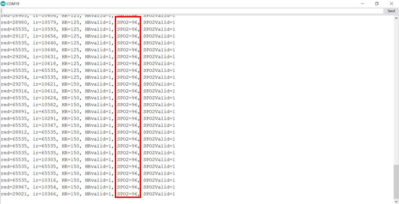
In this code, adding the library as well as adjusting the speed and data transfer rate is done. Notice that the calculation of blood oxygen begins after pressing a desired button.
The results are as follows. As you can see blood oxygen has measured 96.
By following these steps, you can successfully interface the MAX30102 Pulse Oximeter Heart Rate Module with Arduino to detect blood oxygen and heart rate accurately.

Comments (22)
Hi, i follow the procedure that you teach in the website https://electropeak.com/learn/interfacing-max30102-pulse-oximeter-heart-rate-module-with-arduino/. However, my MAX30102 look cannot function since the serial monitor and serial plotter nothing come out. The serial monitor only show the time and does not show any blood oxygen concentration. Your help are greatly appreciated
Hi.
What exactly do you get in the Serial Monitor? If nothing comes out, it could be because the Serial Monitor baud rate is not set correctly. Check the baud rate and make sure it is set to 115200.
Thanks for your reply. The serial monitor show the time only
16:40:04.134 -> InitializiInitializing…
After uploading heart rate,the board memory was almost full..there was no space to include spo2 code.what can I do
The only solution might be replcaing your microcontroller by another one with more memory.
what could be the reason for incorrect readings for both HR and spoo2
Using filters might help you get more precise data. But if the data read is too far from the correct values, the module is probably defective.
Can i use a 9600 baud rate instead because i am using another sensor at the same time and it uses 9600 baud rate and i want both to work in the same time, or is there any way i can use two baud rates in the same Arduino code?
Hi. Yes, you can use change the baud rate to 9600. Generally speaking, when you have more than one sensor with different baud rates, it is suggested that you set the baud rate according to the slowest one, which in your case is 9600.
Hi
Sensor is not connected or not turned on …
Can you help me?
Hi,
What do you see in the Serial Monitor after you upload the code? Also make sure that the baud rate of the Serial Monitor is set to right value which is 115200.
If you have set it and no difference is made, try the “i2c scanner” code and see if any I2C device is recognized. You can find the “i2c scanner” code among the Arduino IDE examples in “File → Examples → Wire → i2c_scanner”.
Click SEND on Serial Monitor.
I was wondering what would be needed to say monitor the blood oxygen result and if it fell below a set value for a set time complete a circuit like a buzzer being sounded… and would the proccessing of that be able to be done the max30102 or what chip would be small like the max30102 itself say it was for a small wearable to tell if your blood oxygen fell below a value for a set time to trigger and action or a circuit
Hi,
You can do what you want using this module. As you can see in Step 4, blood oxygen has been detected, stored in “spo2” variable and displayed on the Serial Monitor. So, you can access blood oxygen can be accessed using the same code. The only thing you need to do is to set a value in the code and check if the “spo2” variable is below that value. In case it has fallen below that certain value, you can activate a buzzer or do anything else.
When the sensor is say in a wearable is MAX30102 the only thing that is needed other than power or does the max30102 need the Arduino to function or is that just to program the sensor? Other than a voltage to power the sensor.. sry I’m just a beginner and was thinking about trying to make this sensor work and monitor just spo2 once every min and if it fell below a set value for 3 consecutive readings than trigger a linear actuator the sensor would be in contact with the skin always
Hi,
Are there any tips to get accurate spo2 readings? I can’t get mine to provide accurate readings it only gives me -999 or other random numbers like 59 or 76 which can’t be accurate.
hi
i need how to display only spo2 and heart rate on LCD using max30102 with arduino uno
Hi,
You can use the following tutorials to see how you can do that.
https://electropeak.com/learn/interfacing-character-lcd-display-modules-with-arduino/
https://electropeak.com/learn/interfacing-i2c-16×2-character-lcd-1602-display-module-with-arduino/
hi, I have run the code but giving me heart rate of 0 what might be the problem?
Hi joylene,
Use the I2C Scanner from the examples in the Arduino IDE to check if the wiring is correct and ensure that the ID from the sensor is valid.
Also, which Arduino board are you using with this sensor?
do you know any software are online circuit diagram web to design the following circuit?
https://wokwi.com/projects/374086706575916033