Interfacing PC817 4-Channel Optocoupler Module with Arduino
Written by
Mohammadreza Akbari
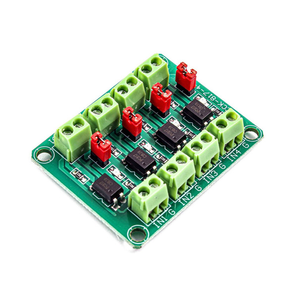
PC817 Optocoupler Module Features
An Optocoupler, is an electronic component that interconnects two separate electrical circuits by means of a light sensitive optical interface. There is a is a light emitting diode with a phototransistor inside the optocouplers, both of them are isolated from the external environment of the optocoupler; This means that the internal phototransistor can only receive light emitted by the internal light emitting diode. The phototransistor base is stimulated by light received from a light emitting diode and can pass current according to it.
Opto-couplers are used where two circuits need to be separated and isolated. For example, when we want the control circuit (for example, processors) to be separate from the power circuit (for example, relays, motors, etc.) we use optocoupler to remove the power circuit noise on control circuit.
Warning
Optocouplers have a low output current. For example, the maximum output current for PC817 is 50 mA. As a result, you cannot connect high current components (such as motors, etc.) to the optocoupler output directly. You need to use a transistor to supply current in such cases.
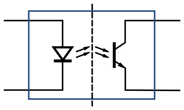
The Internal construction of optocouplers is like this:
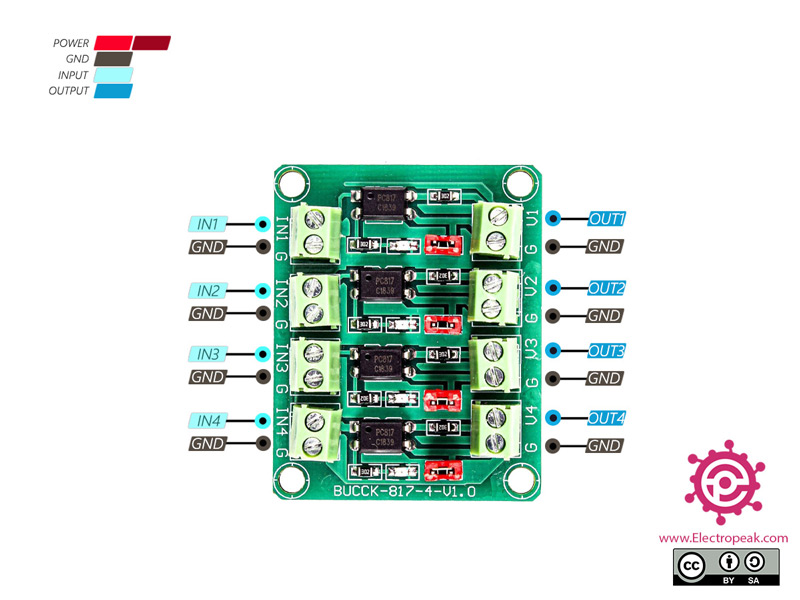
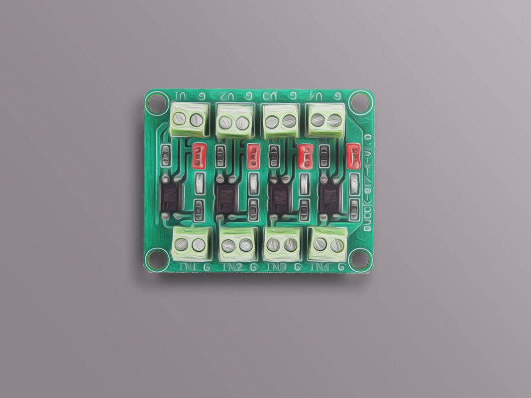
PC817 Optocoupler Module Pinout
Each PC817 channel has 4 pins:
Input pins:
IN: Input – 5 to 30 V
GND: Ground
Output pins:
OUT: Phototransistor collector pin
GND: Phototransistor emitter pin
You can see pinout of this module in the image below.
Note
There is a jumper for each channel. If the jumper is connected, the G pins of input and output are connected to each other. But if the jumper is not connected, the two pins are separate.
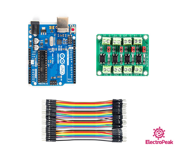
Required Materials
Hardware Components
Arduino UNO R3
×
1
PC817 Optocoupler Module
×
1
Male to Female jumper wire
×
1
Software Apps
Arduino IDE
Interfacing PC817 Optocoupler Module with Arduino
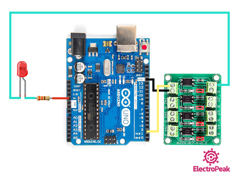
Step 1: Circuit
The following circuit shows how you should connect Arduino to PC817 module. Connect wires accordingly.
Step 2: Code
Upload the following code to your Arduino. This code continuously connects the Optocoupler input for 1 second and disconnects for 1 second.
/*
PC817 Optocoupler
modified on 29 Sep 2020
by Mohammad Reza Akbari @ Electropeak
This tutorial defeats the core purpose of the optocoupler, by just having Arduino alone and connecting both input and output to the same circuit.
Should have included an isolated high voltage section on the output side, to make this tutorial complete.
Thanks for this. What I would like to see is how to use this module to detect voltages rather than control fans etc. Specifically, I would like to monitor 24 Volt HVAC systems so that I can determine when a thermostat or other 24 Volt AC signal is present.
Hi Steve,
You can’t use this module to detect 24VAC voltage.
If you only need to detect the presence of voltage in your system, you can use a diode or a full bridge rectifier with a capacitor (10nF) at the output. This will convert 24VAC to approximately 33.9VDC (24VAC x √2). Next, you can use a voltage divider to scale this voltage down to a safe level for your microcontroller (e.g., divide by 10 using 100K ohm and 10K ohm resistors to get 3.39VDC) and feed this voltage into the ADC of your microcontroller.
If you don’t have a microcontroller and just want a logic output indicating the presence of voltage, you can use an LM358-based circuit to achieve this.


Comments (6)
This tutorial defeats the core purpose of the optocoupler, by just having Arduino alone and connecting both input and output to the same circuit.
Should have included an isolated high voltage section on the output side, to make this tutorial complete.
Hello, thank you for your suggestion. We will incorporate your feedback and update the article accordingly.
A circuit diagram of the PC817 Optocoupler Module would have been useful. Far more useful than five photographs of it.
You are right billy.
Thanks for this. What I would like to see is how to use this module to detect voltages rather than control fans etc. Specifically, I would like to monitor 24 Volt HVAC systems so that I can determine when a thermostat or other 24 Volt AC signal is present.
Hi Steve,
You can’t use this module to detect 24VAC voltage.
If you only need to detect the presence of voltage in your system, you can use a diode or a full bridge rectifier with a capacitor (10nF) at the output. This will convert 24VAC to approximately 33.9VDC (24VAC x √2). Next, you can use a voltage divider to scale this voltage down to a safe level for your microcontroller (e.g., divide by 10 using 100K ohm and 10K ohm resistors to get 3.39VDC) and feed this voltage into the ADC of your microcontroller.
If you don’t have a microcontroller and just want a logic output indicating the presence of voltage, you can use an LM358-based circuit to achieve this.