
Overview
In this article we want to show you how to improve the security of your digital data stored in a hard drive by a finger print sensor and Arduino.
What You Will Learn
- Will learn how to use finger print sensor.
- Will make a security add on for your hard drive.
- Can give access to specific users to use your data bank.
Data Banks Security
A hard disk drive (HDD), hard disk, hard drive, or fixed disk, is an electromechanical data storage device that uses magnetic storage to store and retrieve digital information using one or more rigid rapidly rotating disks (platters) coated with magnetic material. The platters are paired with magnetic heads, usually arranged on a moving actuator arm, which read and write data to the platter surfaces. Data is accessed in a random-access manner, meaning that individual blocks of data can be stored or retrieved in any order and not only sequentially. HDDs are a type of non-volatile storage, retaining stored data even when powered off.
Flash memory is an electronic (solid-state) non-volatile computer storage medium that can be electrically erased and reprogrammed.
Toshiba developed flash memory from EEPROM (electrically erasable programmable read-only memory) in the early 1980s and introduced it to the market in 1984. The two main types of flash memory are named after the NAND and NOR logic gates. The individual flash memory cells exhibit internal characteristics similar to those of the corresponding gates.
While EPROMs had to be completely erased before being rewritten, NAND-type flash memory may be written and read in blocks (or pages) which are generally much smaller than the entire device. NOR-type flash allows a single machine word (byte) to be written – to an erased location – or read independently.
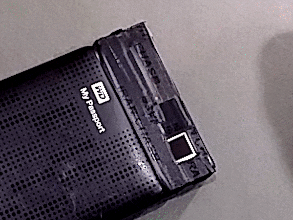
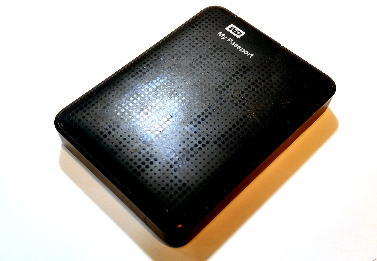
If you use hard drives or flash memories to store your data and they do not have any security on their hardware or software, this project is very useful for you.
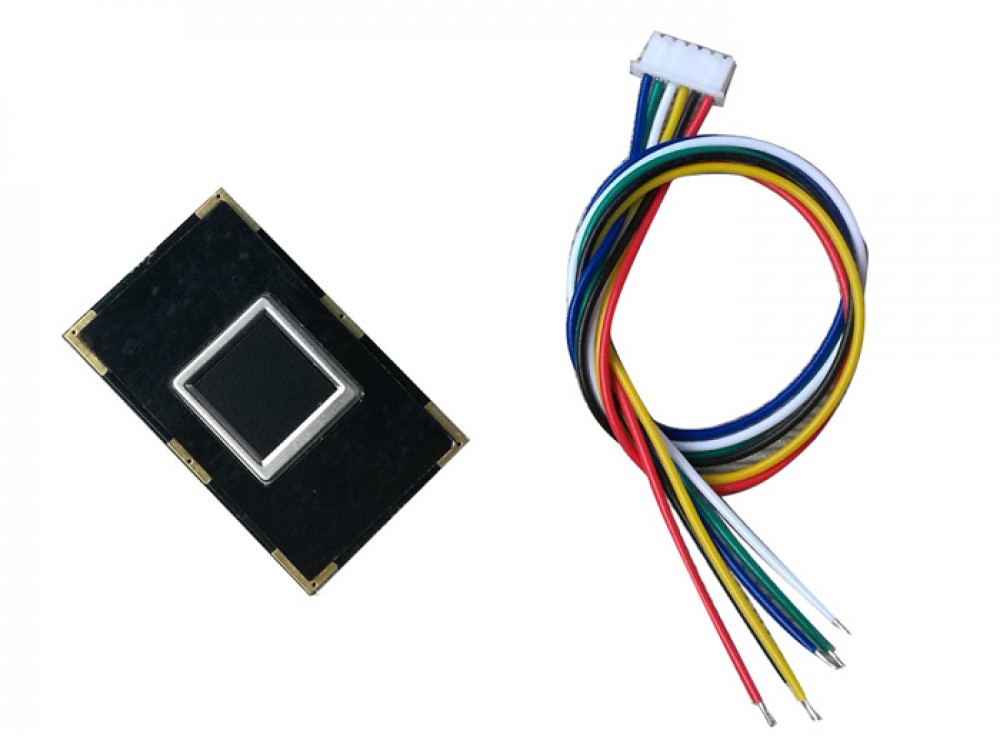
R301T Fingerprint Module
A fingerprint in its narrow sense is an impression left by the friction ridges of a human finger. The recovery of fingerprints from a crime scene is an important method of forensic science. Fingerprints are easily deposited on suitable surfaces (such as glass or metal or polished stone) by the natural secretions of sweat from the eccrine glands that are present in epidermal ridges. These are sometimes referred to as “Chanced Impressions”.
In a wider use of the term, fingerprints are the traces of an impression from the friction ridges of any part of a human or other primate hand. A print from the sole of the foot can also leave an impression of friction ridges.
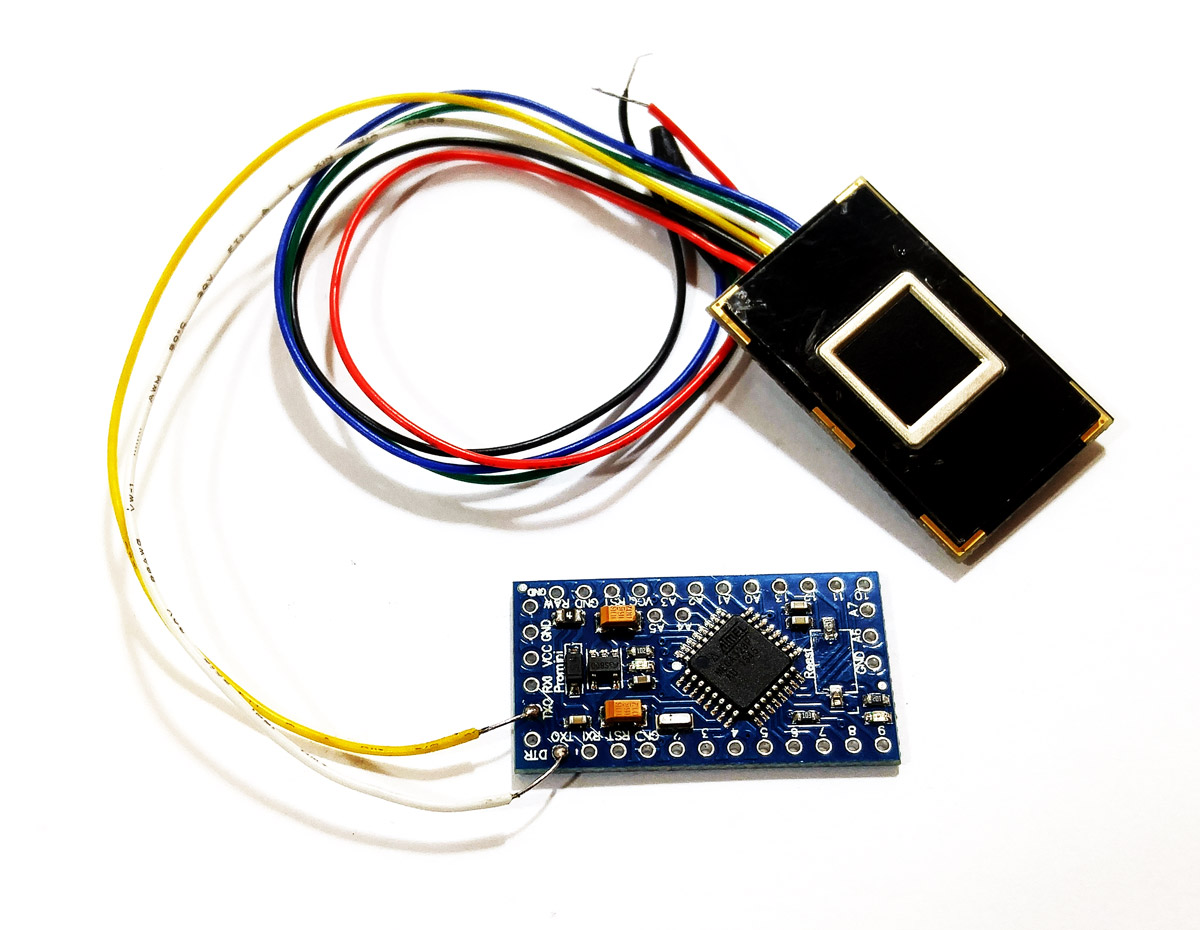
In this project We use R301T sensor module that make an Serial communication with a controller like Arduino to exchange data. Lets do it.
Required Materials
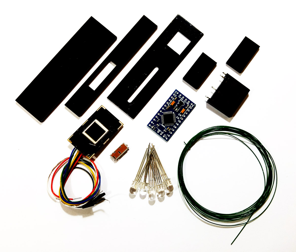
Hardware Components
Software Apps
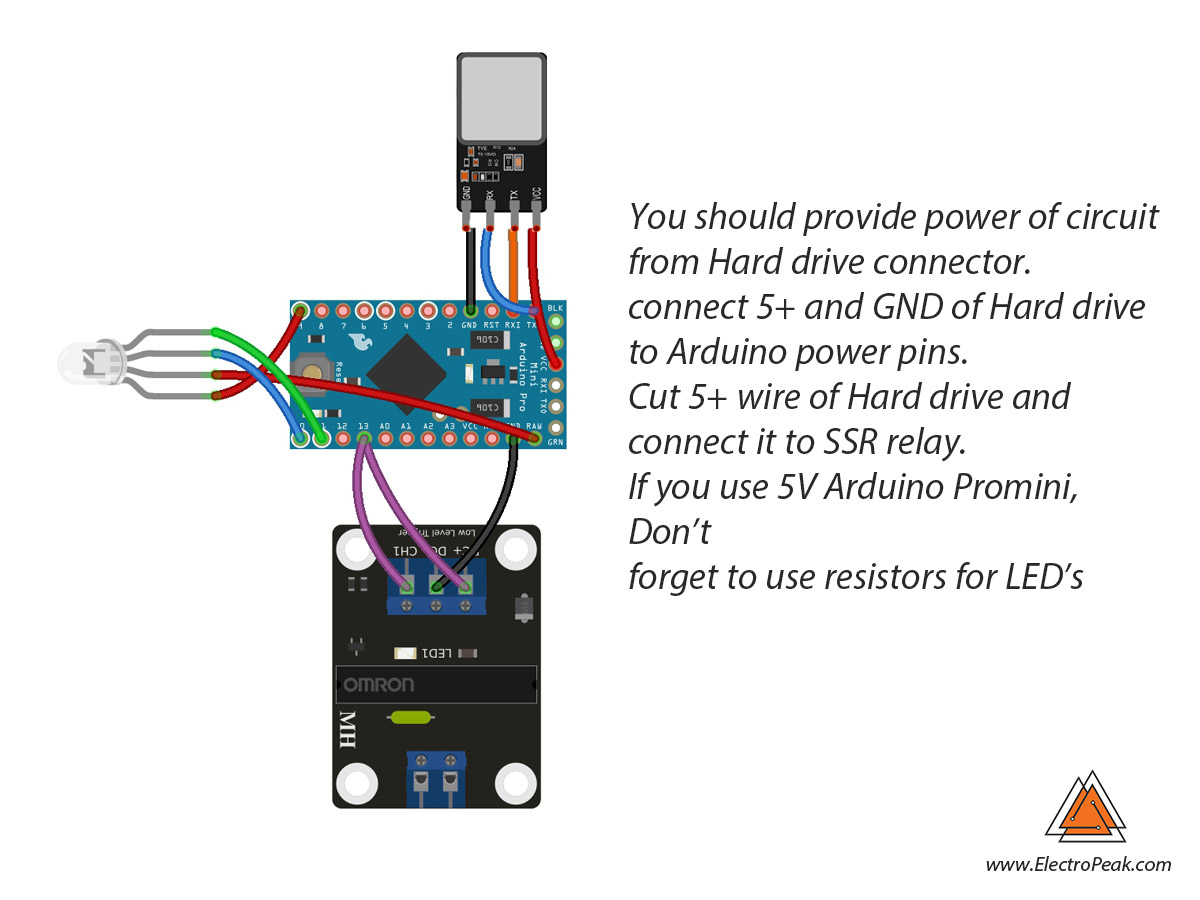
Circuit
Code
You must add the fingerprint sensor’s library and then upload the code. If it is the first time you are using an Arduino board, don’t worry. Just follow these steps:
- Go to www.arduino.cc/en/Main/Software and download the Arduino software compatible with your OS. Install the IDE software as instructed.
- Run the Arduino IDE and clear the text editor and copy the following code in the text editor.
- Choose the board in tools and boards, select your Arduino Board.
- Connect the Arduino to your PC and set the COM port in tools and port.
- Press the Upload (Arrow sign) button.
- You are all set!
Necessary Files and Downloads:
#include "Adafruit_Fingerprint.h"
#include "SoftwareSerial.h"
SoftwareSerial mySerial(2, 3);

Adafruit_Fingerprint finger = Adafruit_Fingerprint(&mySerial);

int cc=0;
void setup()
{
  Serial.begin(9600);
  while (!Serial);  // For Yun/Leo/Micro/Zero/...
  delay(100);
  Serial.println("\n\nAdafruit finger detect test");

  // set the data rate for the sensor serial port
  finger.begin(57600);

  if (finger.verifyPassword()) {
    Serial.println("Found fingerprint sensor!");
  } else {
    Serial.println("Did not find fingerprint sensor :(");
    while (1) { delay(1); }

    pinMode(13,OUTPUT);
    digitalWrite(13,LOW);
    pinMode(9,OUTPUT);
    pinMode(10,OUTPUT);
    pinMode(11,OUTPUT);
    digitalWrite(9,HIGH);
  }

  finger.getTemplateCount();
  Serial.print("Sensor contains "); Serial.print(finger.templateCount); Serial.println(" templates");
  Serial.println("Waiting for valid finger...");
}

void loop()                     // run over and over again
{
  getFingerprintIDez();
  delay(50);            //don't ned to run this at full speed.
}

uint8_t getFingerprintID() {
  uint8_t p = finger.getImage();
  switch (p) {
    case FINGERPRINT_OK:
      Serial.println("Image taken");
      break;
    case FINGERPRINT_NOFINGER:
      Serial.println("No finger detected");
      return p;
    case FINGERPRINT_PACKETRECIEVEERR:
      Serial.println("Communication error");
      return p;
    case FINGERPRINT_IMAGEFAIL:
      Serial.println("Imaging error");
      return p;
    default:
      Serial.println("Unknown error");
      return p;
  }

  // OK success!

  p = finger.image2Tz();
  switch (p) {
    case FINGERPRINT_OK:
      Serial.println("Image converted");
      break;
    case FINGERPRINT_IMAGEMESS:
      Serial.println("Image too messy");
      return p;
    case FINGERPRINT_PACKETRECIEVEERR:
      Serial.println("Communication error");
      return p;
    case FINGERPRINT_FEATUREFAIL:
      Serial.println("Could not find fingerprint features");
      return p;
    case FINGERPRINT_INVALIDIMAGE:
      Serial.println("Could not find fingerprint features");
      return p;
    default:
      Serial.println("Unknown error");
      return p;
  }

  // OK converted!
  p = finger.fingerFastSearch();
  if (p == FINGERPRINT_OK) {
    Serial.println("Found a print match!");
  } else if (p == FINGERPRINT_PACKETRECIEVEERR) {
    Serial.println("Communication error");
    return p;
  } else if (p == FINGERPRINT_NOTFOUND) {
    Serial.println("Did not find a match");
    return p;
  } else {
    Serial.println("Unknown error");
    return p;
  }

  digitalWrite(9,LOW);
  // found a match!
  for (int i=0;i>5;i++)
  {digitalWrite(10,LOW);
  delay(10);
  digitalWrite(10,HIGH);
  delay(10);}
  Serial.print("Found ID #");
  Serial.print(finger.fingerID);
  Serial.print(" with confidence of ");
  Serial.println(finger.confidence);
  for (int i=255;i>1;i--)
{analogWrite(11,i); delay(10);}
  digitalWrite(13,HIGH);
  return finger.fingerID;
}

// returns -1 if failed, otherwise returns ID #
int getFingerprintIDez() {
  uint8_t p = finger.getImage();
  if (p != FINGERPRINT_OK)  return -1;

  p = finger.image2Tz();
  if (p != FINGERPRINT_OK)  return -1;

  p = finger.fingerFastSearch();
  if (p != FINGERPRINT_OK)  return -1;

  // found a match!
  Serial.print("Found ID #"); Serial.print(finger.fingerID);
  Serial.print(" with confidence of "); Serial.println(finger.confidence);
  return finger.fingerID;
}
Assembling
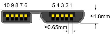
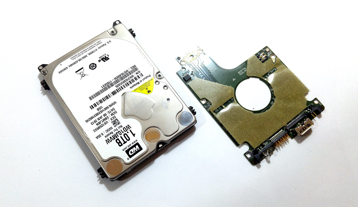
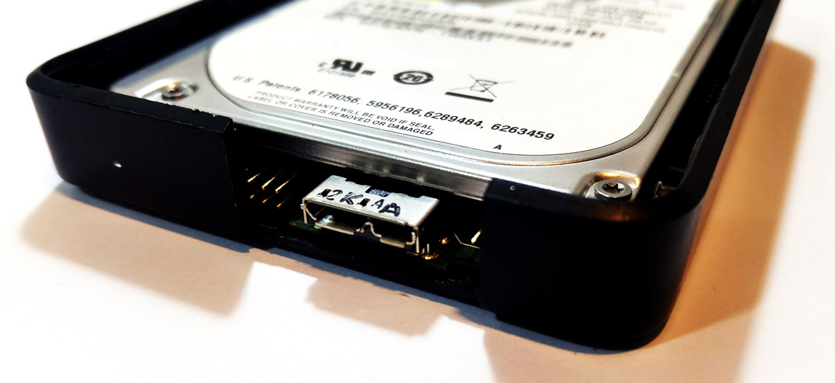
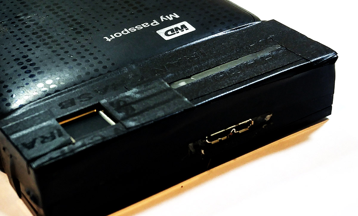
First, Make a small cable connector by micro USB 3 socket. To find out the pin map of socket, use board of Hard Drive.

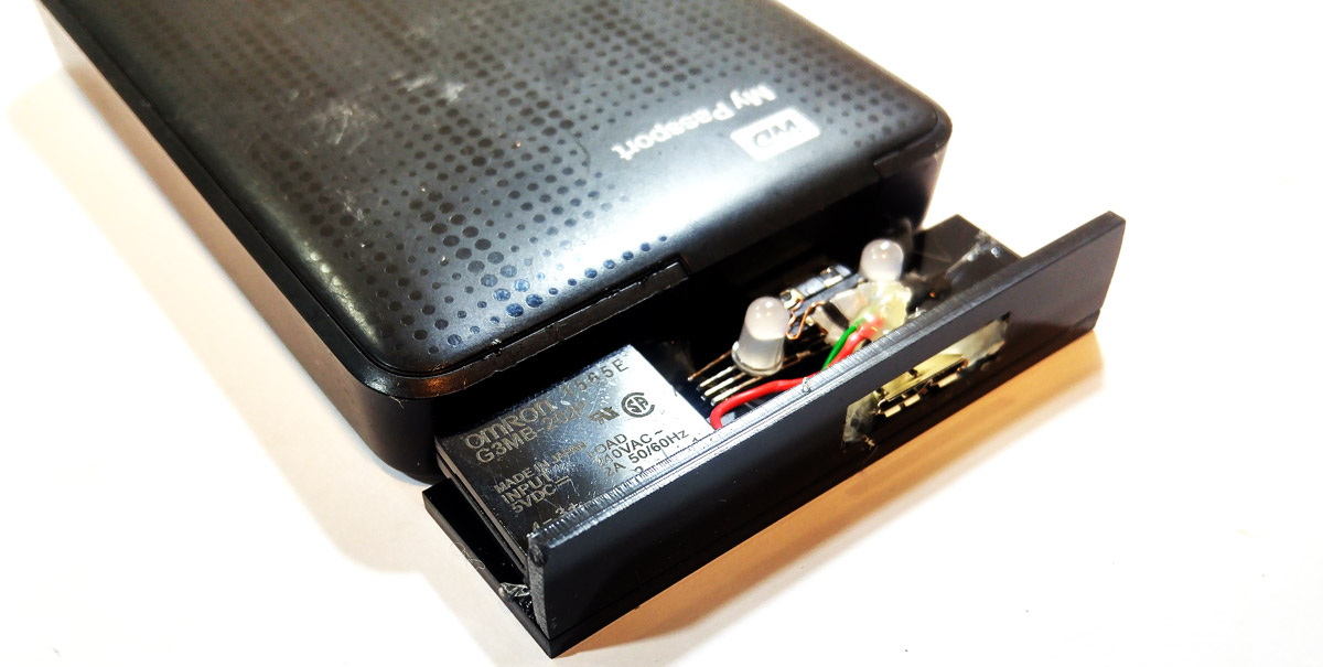
Make a box with Acrylic sheet (plexiglass) and put the circuit in it .
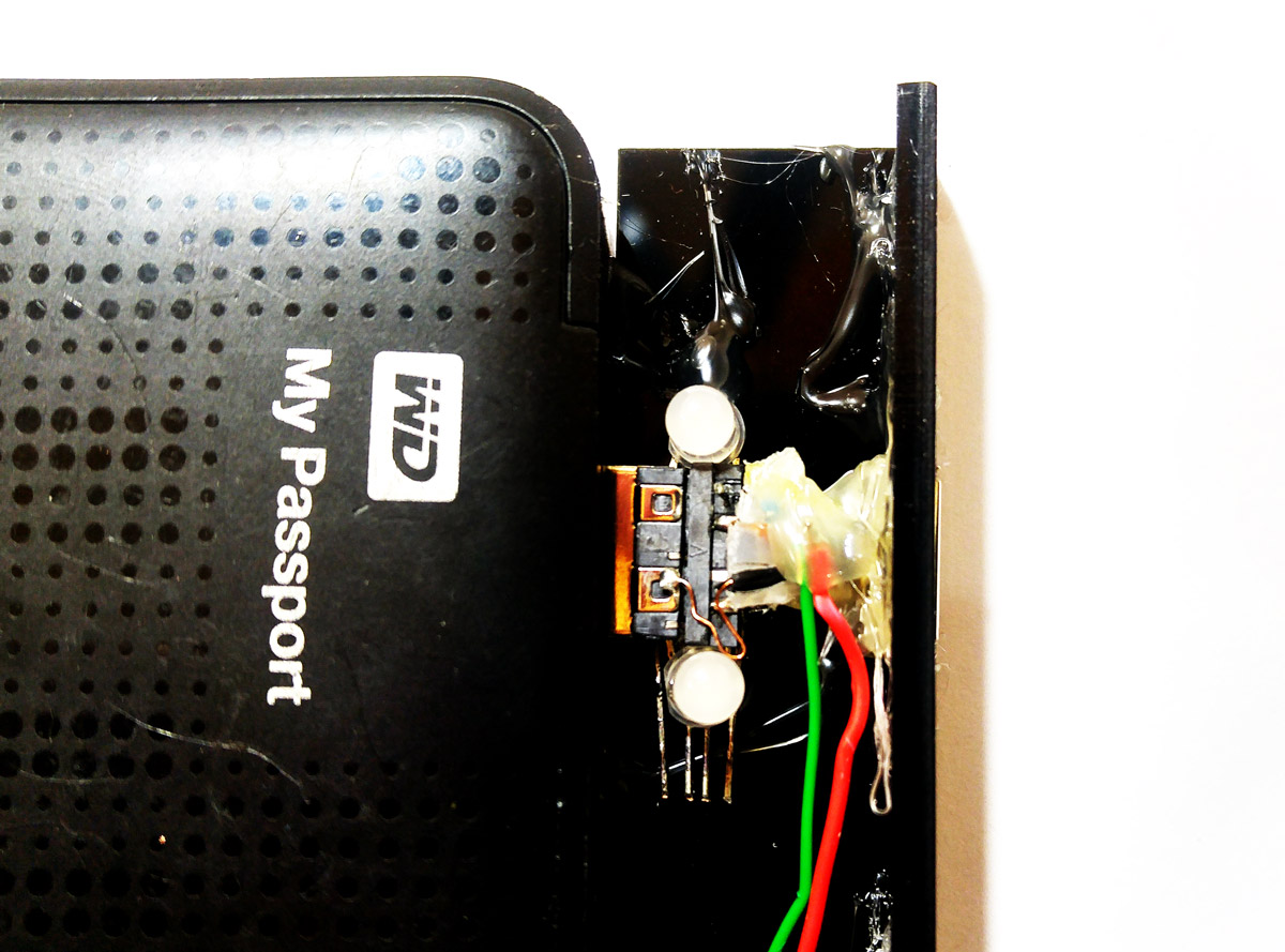
Separate relay from the board and connect it to Arduino directly.
What’s Next?
You can improve this project as you wish. Here are a few suggestions:
- Try to store time of connection by each user in Arduino.
- Try to calculate the amount of data transferred by each user.

Comments (4)
Your project is very nice. I want to ask you a question about assembly. How did you connect the Micro USB 3.0 Connector to the arduino promini? printed a pcb or soldering wire? Can you give more information about this?
Thanks for your comment, you can use usb3.0 breakout
Hi Your project is awesome. Can i get its circuit diagram?
Hi. You’re welcome
The circuit diagram is provided in the article. You can see it in the “circuit” section right below the “Hardware Components” and “Software Apps”.