Product added to cart

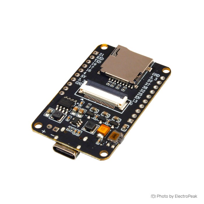
ESP32-CAM Plus Development Board With OV5640 Camera
$17.5000
In stock
SKU
DEV-02-025
Volume discounts:
- +25 4 % $16.8400
- +50 6 % $16.5100
- +100 8 % $16.1800
- +300 9 % $15.8500
- +500 11 % $15.5200
Ships in 2-3 business days, then:
Free delivery in10-15 days by YunExpress on orders over $35.
Free delivery in5-7 days by DHL on orders over $200.
More shipping info

Shop with confidence Learn More
 ESP32-CAM Development Board With OV3660 Camera and Mainboard Previous
The ESP32-CAM Plus Development Board with OV5640 Camera is a powerful and versatile development board designed for advanced image processing and wireless communication. Powered by an Xtensa® 32-bit LX6 dual-core processor, it supports up to 600 MIPS computing power and integrates a 5MP OV5640 camera. Ideal for IoT applications, it features WiFi and Bluetooth connectivity, supports multiple operating systems, and offers real-time camera access via a web interface. This board is perfect for security cameras, smart home devices, and wireless video transmission.
Specifications of ESP32-CAM Plus Development Board With OV5640 Camera
-
CPU Frequency: 240MHz (WiFi/BT)
-
Flash Size: 4MB (32Mb)
-
PSRAM: Enabled
-
Max. Resolution: 2592(H) x 1944(V)
-
Focusing Type: Fixed Focus/Auto Focus (selectable)
-
Board Size: 62mm x 9.0mm x 6.4mm
-
Interface: Type-C
-
Field of View (FOV): 72-220 Degrees
-
IR Filter: 650±10nm
-
Operating Temperature: 0°C to 60°C
-
Storage Temperature: 0°C to 60°C
-
Wireless Communication: WiFi 2.4G 802.11 b/g/n, Bluetooth v4.2
-
Power Supply: ---
-
Connector: ---
-
Operating System Support: Windows XP/Vista/7/8, Linux with UVC, macOS X 10.4.8 or later, Android 4.0 or above with UVC
-
Dimensions: 62mm x 9.0mm x 6.4mm
How to use ESP32-CAM Plus Development Board With OV5640 Camera
Using pre-programmed code:
-
Connect the board to your computer or power source using a USB Type-C cable.
-
The red LED status light will turn on, indicating that the board is powered.
-
On your computer or mobile device, search for the WiFi network named "ESP32_CAM" and connect to it.
-
Once connected, open a web browser and enter the IP address 192.168.4.1 to access the camera's video feed in real-time.
-
Use the interface to adjust settings and monitor the video stream.
Using Arduino and your own code (just like ESP32-CAM):
To set up the ESP32-CAM Plus module in the Arduino environment, follow these steps:
1. Modify the camera_pins.h file:
Add the following lines:
#elif defined(CAMERA_MODEL_ESP32_CAM_PLUS)
#define PWDN_GPIO_NUM       -1
#define RESET_GPIO_NUM      5
#define XCLK_GPIO_NUM       15
#define SIOD_GPIO_NUM       22
#define SIOC_GPIO_NUM       23

#define Y9_GPIO_NUM         39
#define Y8_GPIO_NUM         34
#define Y7_GPIO_NUM         33
#define Y6_GPIO_NUM         27
#define Y5_GPIO_NUM         12
#define Y4_GPIO_NUM         35
#define Y3_GPIO_NUM         14
#define Y2_GPIO_NUM         2
#define VSYNC_GPIO_NUM      18
#define HREF_GPIO_NUM       36
#define PCLK_GPIO_NUM       26

#define LED_GPIO_NUM        25
2. Edit the CameraWebServer sketch:
Comment out all other camera models, and add the following line at the end:
#define CAMERA_MODEL_ESP32_CAM_PLUS // Has PSRAM
3. Optional:
You can download the preconfigured file below, upload it directly to your board, and just set your WiFi SSID and password:
Write Your Own Review

Please complete your information below to login.
Sign In
Create New Account