
Product added to cart

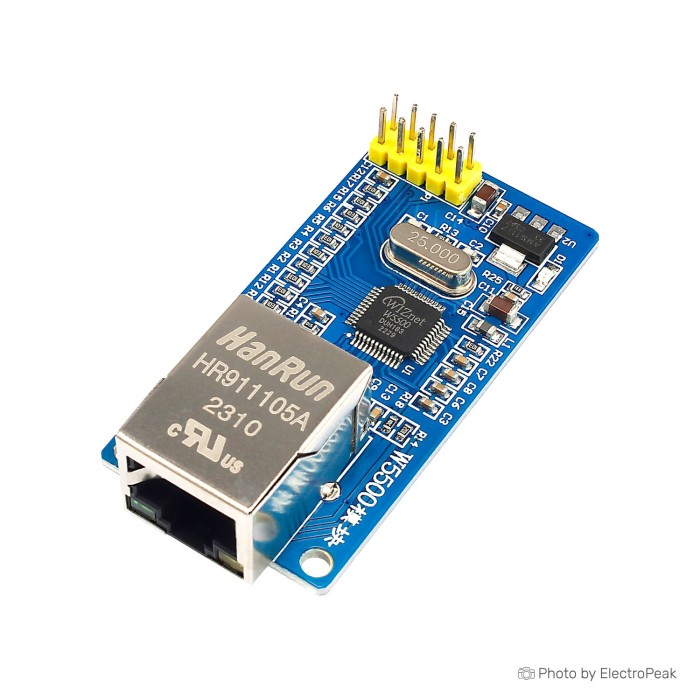
W5500 TCP/IP Ethernet Network Module
$3.2500
In stock
SKU
COM-04-011
Volume discounts:
- +25 4 % $3.1300
- +100 6 % $3.0600
- +300 8 % $3.0000
- +500 10 % $2.9400
- +1000 11 % $2.8800
Ships in 2-3 business days, then:
Free delivery in 12-15 days by Tracked Economic Shipping on orders over $100.
Free delivery in 7-10 days by Express Shipping on orders over $300.
More shipping info

Shop with confidence Learn More
 Breadboard Power Supply Module - 3.3V/5V Previous
W5500 TCP/IP Ethernet Network Module Review and Specifications
The W5500 TCP/IP Ethernet Network Module is an SPI-connected network breakout built around the Wiznet W5500 controller, with an integrated RJ-45 port and a hardwired IPv4 TCP/IP stack. It connects small microcontrollers directly to a local area network without placing a complex, memory-heavy software network stack on the host chip. The board suits developers building wired embedded nodes who can verify their board's pinout, regulate power supply levels, configure chip-select lines, and define unique MAC addresses in firmware. It is not a USB Ethernet adapter, router, switch, serial device server, or Wi-Fi radio.
The underlying WIZnet W5500 controller provides hardware protocol offload and broad embedded library support. This specific breakout, however, is a generic board implementation without manufacturer revision tracking, published schematic details, or factory-provisioned MAC addresses. Plan power routing, GPIO assignments, and firmware configuration carefully before connecting it to your system. Reliable operation depends on it.
Specifications of W5500 TCP/IP Ethernet Network Module
- Controller: Wiznet W5500
- RJ-45 port
- Supports wired TCP/IP protocols: TCP, UDP, ICMP, IPv4, ARP, IGMP, PPPoE
- It supports up to 8 simultaneous connections so it is suitable for use in different SCM systems.
- Compatible with all Microcontroller like Arduino and ESP
- Transmission rate: 10/100 MBPS
- Power supply: 3.3 V or 5 V
- Communication: SPI
- Supports 8 independent plugs simultaneously
- Supports shutdown mode
- Supports Wake on LAN over UDP
- Supports a high-speed serial peripheral interface (SPI MODE 0, 3)
- 32Kbyte internal memory for TX/RX buffers
- 10BaseT/100BaseTX Ethernet PHY built-in
- Supports self-negotiation (Full and half duplex, 10 and 100-based )
- Does not support IP fragmentation
- 3.3V operation with 5V I/O signal tolerance
- LED outputs (Full/Half duplex, Link, Speed, Active)
- Dimensions: 59 x 36 mm
W5500 SPI Ethernet Module Specifications Explained
Evaluating this module for an embedded build means separating physical link capability from achievable microcontroller throughput. The integrated 10BaseT/100BaseTX physical layer (PHY) negotiates full- or half-duplex links at 10 Mbps or 100 Mbps with standard Ethernet switches. That rate defines wire speed on the local cable run, not application throughput. Actual payload throughput depends on the host microcontroller's processing speed, SPI bus frequency, buffer management, and firmware overhead. WIZnet controller family benchmarks indicate maximum network performance of up to 50 Mbps under optimal host conditions, while low-speed microcontrollers deliver more modest real-world payload rates.
The WIZnet W5500's defining feature is its hardwired TCP/IP core. By executing TCP, UDP, ICMP, IPv4, ARP, IGMP, and PPPoE directly in silicon, the chip avoids the RAM and flash footprint needed for software network stacks such as lwIP on minimal 8-bit or 32-bit MCUs. Builders intentionally choosing a simpler MAC/PHY controller without integrated hardware protocol offloading can use the ENC28J60 Ethernet Module, which places all socket-state handling and protocol decoding directly in the host processor's memory.
| Specification | Hardware Value | Why It Matters in Practice |
|---|---|---|
| Ethernet PHY | 10/100 Mbps auto-negotiation | Negotiates automatically with modern switches; wire link rate differs from application payload transfer rate. |
| Hardware Offload | TCP, UDP, ICMP, IPv4, ARP, IGMP, PPPoE | Frees microcontroller SRAM and flash by running the transport and network layers entirely on-chip. |
| Internal Memory | 32 KB total TX/RX buffer | Comprises 16 KB transmit and 16 KB receive buffers allocated dynamically among open communication sockets. |
| Hardware Sockets | Up to 8 independent sockets | Permits up to eight concurrent client or server communication endpoints managed simultaneously via firmware. |
| Host Interface | SPI (Modes 0 and 3) | Connects through standard four-wire SPI buses up to 80 MHz clock rates, compatible with standard MCU peripherals. |
| IP Fragmentation | Not supported | Packets exceeding the local maximum transmission unit (MTU) are dropped; MTU negotiation must avoid fragmented frames. |
| Addressing | IPv4 stack | Designed strictly for IPv4 environments; native IPv6 dual-stack addressing is unsupported on this controller. |
| Power Modes | Shutdown and Wake on LAN over UDP | Allows putting the PHY into low-power states and waking on UDP magic packets when host wiring supports it. |
The 32 KB internal buffer is shared across all active sockets: 16 KB is allocated for transmission and 16 KB for reception. Firmware can apportion buffer sizes per socket, for example by assigning larger 8 KB buffers to high-volume connections while leaving smaller 1 KB or 2 KB buffers for lightweight telemetry. The eight simultaneous connections refer only to internal socket registers, not multiple physical Ethernet jacks.
W5500 SPI Ethernet Module Compatibility and First Test
Connecting the module requires an SPI-capable microcontroller, five to six digital signal lines, clean power, a common ground, and a reliable network patch cable such as a Crossover Ethernet Cable - 1m for direct link tests or standard patch wiring to a local switch. It interfaces with Arduino Uno, Mega, ESP32, ESP8266, STM32, and RP2040 boards through SPI Modes 0 or 3 using standard SCK, MOSI, MISO, and a dedicated Chip Select (CS) line.
Power integration demands close attention to labeling. The W5500 IC operates internally at 3.3 V and has 5 V-tolerant I/O pins. Generic breakout listings state a 3.3 V or 5 V power supply, but onboard voltage regulation and traces vary across manufacturing runs. If the board has a dedicated 3V3 input pin, supply clean 3.3 V capable of delivering at least 200 mA during peak Ethernet transmission. Apply 5 V only if the module clearly routes power through a verified onboard linear regulator input, often labeled VIN or 5V. Never apply 5 V directly to a pin designated 3V3.
| System Area | Requirement / Setting | Integration Guidance |
|---|---|---|
| Host Hardware | Microcontroller with SPI master port | Supports Arduino, ESP32, ESP8266, STM32, and RP2040 microcontrollers. |
| SPI Signals | SCK, MOSI, MISO, CS | Requires dedicated Chip Select line; MISO and MOSI connect to primary hardware SPI lines. |
| Operating Voltage | 3.3 V logic (5 V tolerant I/O) | Ensure stable 3.3 V rail with >200 mA margin; verify regulator presence before feeding 5 V. |
| Network Layer | IPv4 configuration | Assign static IP or establish an active DHCP server on the connected subnet. |
| Physical Cable | RJ-45 Cat5e/Cat6 patch cable | Connect to a 10/100/1000 switch, router port, or direct endpoint. |
For builders who need an established Arduino form factor with integrated storage, the W5100 Arduino Shield V1 plugs directly onto Uno or Mega footprints and includes an onboard SD card slot. For a compact, standardized custom-PCB footprint, consider the W5500 Module (WIZ820io Compatible), which provides the known 23 x 25 mm pinout layout.
To verify module functionality upon arrival, follow this testing workflow:
- Examine the board's header silkscreen to confirm pin order for Ground, Power, SCK, MISO, MOSI, and CS.
- Wire Ground, 3.3 V power, and the four SPI signal lines to your microcontroller development board.
- Plug an active Ethernet cable into the RJ-45 jack and confirm that physical switch link lights turn on.
- Install an updated W5500-compatible library, such as the standard Arduino Ethernet library or ESP-IDF network component.
- Explicitly define your active CS pin in the firmware initialization function rather than relying on default shield pin numbers.
- Configure a distinct MAC address in code and initialize DHCP or a static IPv4 subnet address.
- Run a simple network ping or open a basic HTTP client connection to confirm data reception.
When sharing the SPI bus with displays or SD card readers, every peripheral needs its own Chip Select GPIO. Unselected devices must be pulled high to remain inactive, preventing bus contention that disrupts Ethernet communication.
W5500 Ethernet Module Limitations and Troubleshooting
Several hardware limitations and documentation gaps need attention when working with this generic module. The W5500 controller handles IPv4 traffic exclusively; its hardware parser does not recognize native IPv6 packets. It also lacks support for IP packet fragmentation. Any incoming fragmented IP packet will not be processed correctly, making proper MTU sizing critical across your local network.
Keep throughput figures in realistic context. The W5500's 80 MHz rating is its maximum SPI bus clock frequency, not a network payload data rate. Real network throughput reaches around 50 Mbps under laboratory conditions, while typical MCU configurations run substantially lower because of SPI transaction overhead and application processing cycles.
Specific hardware features remain unstandardized because this is a generic module. Physically measure silkscreen labels, reset trace breakouts, interrupt (INT) pin routing, and board dimensions, listed nominally at 59 x 36 mm, before designing permanent enclosures. One community project evaluating prototype stability reported that board-level assembly and soldering quality on generic modules can introduce intermittent connection faults, requiring validation under vibration or temperature extremes. This is a family-level observation, not proof of a defect in this SKU. For applications needing isolated field power or hardware interrupt routing, the W5500 alternative W5100 R3-2013 Arduino Shield provides an INT jumper and IEEE 802.3af isolated power circuitry.
Review these common troubleshooting scenarios when you encounter initial setup issues:
- DHCP fails or controller not found: The host MCU is failing to communicate over SPI. Verify that the CS pin defined in firmware exactly matches the physical GPIO wired to the module. Ensure MISO and MOSI are not reversed.
- No link light on the RJ-45 socket: Check the patch cable and switch port connection. The PHY requires adequate operating current; verify that the 3.3 V supply line does not dip below nominal levels during link auto-negotiation.
- Duplicate network collisions: Generic modules do not contain factory-burned unique MAC addresses. If multiple modules run on the same LAN with identical example sketch MAC values, routing conflicts will crash connections. Assign a distinct MAC in host firmware for every deployed board.
- Software library errors on ESP32 or ESP8266: Platform core updates occasionally alter third-party SPI Ethernet bindings. Specify SPI pin maps explicitly in setup code and test dependencies against verified library releases.
- Wake on LAN does not wake the host MCU: The W5500 controller detects UDP magic packets, but waking the host microcontroller requires routing the module's interrupt pin to a wake-capable GPIO and configuring system sleep states in code.
W5500 Ethernet Module Projects and Embedded Uses
Its offloaded transport engine lets the W5500 operate efficiently where microcontrollers need dependable LAN connectivity without sacrificing system resources. WIZnet's official firmware drivers provide standard implementations for core network services including DHCP, DNS, MQTT, SNTP, TFTP, and embedded HTTP servers.
Practical embedded applications suited to this module include:
- Wired telemetry nodes: Environmental monitors and factory sensor gateways transmitting telemetry to central servers through MQTT or HTTP POST requests over an interference-free wired medium.
- Local web control panels: Microcontrollers serving lightweight HTML and JSON status endpoints for local browser control of relays, indicators, and machinery.
- Fixed building automation: Access monitors, lighting controllers, and HVAC interfaces in facilities where wireless signals are obstructed or restricted by security policy.
- Modbus TCP endpoints: Industrial telemetry units bridging standard GPIO or serial inputs to industrial Ethernet systems through microcontroller-based Modbus protocol translation.
- Network-synchronized loggers: Data acquisition nodes using SNTP to pull accurate network time stamps before recording data to local non-volatile memory.
This module provides network interface controller functions, not standalone device functionality. It cannot work independently as a USB Ethernet dongle, print server, or network camera without an external host processor executing application firmware. Custom network installations often require terminating cables directly at terminal blocks or enclosures; this can be done with an RJ45 CAT6 Ethernet Connector.
W5500 vs ENC28J60 and W5100 Ethernet Module Alternatives
Selecting an embedded Ethernet module means weighing protocol offload capability, interface type, socket capacity, and board form factor. The W5500 combines eight hardware sockets with SPI simplicity, though other controller architectures may better suit particular microcontroller peripherals or enclosure constraints.
| Module / Chip | Network Stack Type | Link Speed | Host Interface | Sockets / Buffers |
|---|---|---|---|---|
| W5500 Module | Hardware TCP/IP | 10/100 Mbps | SPI (Modes 0, 3) | 8 sockets / 32 KB buffer |
| ENC28J60 Module | MAC/PHY only (Host stack) | 10 Mbps | SPI | Host-managed / 8 KB buffer |
| W5100 Breakout | Hardware TCP/IP | 10/100 Mbps | SPI or Parallel Bus | 4 sockets / 16 KB buffer |
| W5100 Arduino Shield V1 | Hardware TCP/IP | 10/100 Mbps | SPI (Shield header) | 4 sockets / 16 KB buffer |
| LAN8720 / DP83848 | PHY transceiver only | 10/100 Mbps | RMII / MII | Managed by host MAC |
Against the ENC28J60 Ethernet Module, the W5500 reduces the burden on memory-constrained MCUs by handling protocol layers internally and negotiating 100 Mbps links. The ENC28J60 operates at 10 Mbps and requires the host processor to run a software stack such as uIP or lwIP.
The W5100 Ethernet Breakout Module supports parallel microcontroller buses alongside SPI, which suits legacy architectures, but it is limited to four simultaneous hardware sockets and a 16 KB buffer. For standard Arduino boards, the W5100 Arduino Shield V1 and the W5100 R3-2013 Arduino Shield provide convenient stackable headers while retaining the older four-socket limitation.
If your project already uses an advanced microcontroller with an integrated Ethernet MAC, such as certain ESP32, STM32, or NXP microcontrollers, an SPI controller is not required. Physical layer transceivers such as the LAN8720 RMII PHY Module or WaveShare DP83848 PHY Module connect through high-speed RMII or MII interfaces, allowing the microcontroller's internal MAC to manage network frames at higher throughput.
For systems that specifically require native dual-stack IPv4 and IPv6 support in hardware, WIZnet produces the W6100 controller family. The W6100 is not used on this breakout, but it is the direct architectural alternative where IPv6 deployment is an absolute requirement.
W5500 Ethernet Module FAQ, Accessories and Buying Checklist
Frequently Asked Questions
Is this a complete Ethernet adapter for a PC?
No. This is an SPI peripheral module for microcontrollers. It cannot function as a USB Ethernet adapter, network card, or router without an external MCU and dedicated firmware.
Can I use this W5500 module with Arduino?
Yes, it connects to Arduino boards through hardware SPI pins. You must wire Ground, power, SCK, MISO, MOSI, and a digital pin for Chip Select, then configure the board with an updated Ethernet library.
Can I use this module with an ESP32?
Yes, the W5500 can be used with the ESP32 through SPI. Software library implementations have varied across ESP-IDF and Arduino-ESP32 core versions, so explicitly assign your SPI GPIOs and verify library compatibility.
Can I power the W5500 module from 5 V?
Only if your board includes a verified linear voltage regulator connected to a designated 5V or VIN input. The W5500 controller operates strictly at 3.3 V; feeding 5 V into a pin marked 3V3 will permanently damage the chip.
What does 10/100 MBPS mean on this module?
It means the onboard Ethernet PHY supports 10 Mbps and 100 Mbps link auto-negotiation. Actual application payload throughput depends on the host microcontroller's SPI speed and processing overhead, reaching up to 50 Mbps under optimal conditions.
Is the module transfer speed 80 Mbps?
No. The 80 MHz rating is the maximum SPI clock frequency supported by the W5500 interface. It does not represent achievable network data throughput.
Does this module support Wi-Fi?
No, it provides wired Ethernet communication only through its RJ-45 jack.
How many devices can connect to the W5500 simultaneously?
The module provides up to eight independent hardware sockets managed in firmware. It has a single physical RJ-45 port, and practical client capacity depends on buffer allocation and communication protocol design.
Does this module include a unique factory MAC address?
No factory MAC address is provided with this generic board. You must define and assign a unique MAC address in your microcontroller's firmware sketch before deploying it on a network.
Why does W5500 DHCP fail during startup?
DHCP failures occur because of an incorrect Chip Select pin definition in code, loose SPI wiring, inadequate 3.3 V current delivery, or MAC address collisions on the local subnet.
Does the W5500 support IPv6?
No, the hardware protocol parser in the W5500 is built exclusively for IPv4 networks.
Does the module support Power over Ethernet (PoE)?
No, this module lacks PoE extraction circuitry. Connecting it to a passive PoE line without an external splitter can damage the board.
Accessories
Required
- Ethernet patch cable: Crossover Ethernet Cable - 1m for direct testing or switch connections.
- Host microcontroller development board with an accessible SPI bus, such as Arduino, ESP32, STM32, or RP2040.
- Regulated 3.3 V DC power supply capable of supplying at least 200 mA peak current.
- Jumper wires or soldered header connections for SPI bus and power rails.
- Unique MAC address defined in software for each deployed device.
Recommended
- Multimeter or continuity tester to verify board pinout before applying power.
- USB-to-serial adapter or serial monitor connection for runtime diagnostic output.
- Custom Ethernet cabling hardware: RJ45 CAT6 Ethernet Connector for tailored wire runs.
- Protective project enclosure with cable strain relief.
Optional
- Chassis-mounted Ethernet jack: RJ45 Ethernet Unshielded Socket DIP for panel breakouts.
- External active PoE splitter if powering the project over the network line.
- Dedicated reset line connection between host MCU and module reset pin.
Purchase Decision Summary
- Ideal for: Developers needing a reliable wired IPv4 Ethernet connection for microcontrollers through SPI, using hardware TCP/IP protocol offload to conserve host RAM and flash.
- Maybe for: Makers building Arduino or ESP32 prototypes who are comfortable tracing board pinout silkscreens, supplying verified 3.3 V power, and managing MAC addresses in code.
- Consider another option if: You need Wi-Fi, USB plug-and-play operation, native IPv6 support, integrated PoE, hardware IP fragmentation, or an officially certified module with traceable revisions.
Buying Checklist
- [ ] My host microcontroller has an available SPI master port and one free digital GPIO for Chip Select.
- [ ] I have a dedicated 3.3 V power source capable of supplying over 200 mA during network transmission.
- [ ] I can confirm the board's header pinout silkscreen before applying power.
- [ ] My network environment uses standard IPv4 addressing and does not require IPv6.
- [ ] My application does not rely on IP packet fragmentation.
- [ ] I understand this board requires setting a custom MAC address in my firmware.
- [ ] I have an RJ-45 patch cable and an active network switch, router, or endpoint ready.
- [ ] I do not require built-in Power over Ethernet (PoE) or wireless functionality.
| Platform | Arduino Mega, Arduino Uno, Arduino Nano, ESP |
|---|---|
| Interface Type | SPI |
| Operating Voltage (V) | 3.3V, 5V |
| Operating Temp (°C) | -40 to 85 |
| Dimensions (mm) | 59x28 mm |
| Network Protocol | TCP/IP, UDP |
| Data transmission rate | 10/100 Mbps |
| Standard | Ethernet |
| Voltage Levels | 3.3 V, 5 V |
| Chipset | W5500 |
| Indicator LEDs | LINK, Active, Full/Half duplex, Speed |
Write Your Own Review

Please complete your information below to login.
Sign In
Create New Account