
Product added to cart

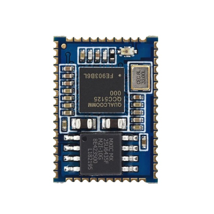
SJR-BTM525 QCC5125 Qualcomm Bluetooth Audio Module
$11.9500
In stock
SKU
MOD-04-009
Volume discounts:
- +25 4 % $11.4700
- +50 6 % $11.2300
- +100 8 % $10.9900
- +300 10 % $10.7500
- +500 12 % $10.5100
Ships in 2-3 business days, then:
Free delivery in 12-15 days by Tracked Economic Shipping on orders over $100.
Free delivery in 7-10 days by Express Shipping on orders over $300.
More shipping info

Shop with confidence Learn More
 Sinilink XY-AP100H HIFI Stereo Bluetooth Power Amplifier Module (100W*2) Previous
SJR-BTM525 QCC5125 Bluetooth Module Review
The SJR-BTM525 is a 13mm × 18mm surface-mount audio module built around the Qualcomm QCC5125 BGA chipset, with Bluetooth 5.1 and low-power operation. It is intended for hardware engineers and experienced audio developers integrating it into custom carrier boards with user-supplied power regulation, RF layout, and analog or digital output stages. Small-quantity pricing sits around $11–12. Builders who need direct 5V operation, plug-and-play Active Noise Cancellation (ANC), pre-configured premium codecs, or verified out-of-the-box AT commands should look to fully integrated Bluetooth audio modules and sound-player hardware instead.
Specifications of SJR-BTM525 QCC5125 Qualcomm Bluetooth Audio Module
- Model Name: SJR-BTM525
- Product Description: Bluetooth 5.1 Class 1.5 Module
- Bluetooth Standard: Bluetooth 5.1
- Chipset: QCC5125 BGA
- Dimension: 13mm x 18mm x 2.8mm
- Voltage: 2.8V - 4.3V
- Operating Temperature: -40°C to +85°C
- Storage Temperature: -40°C to +85°C
- Frequency Range: 2402MHz - 2480MHz
- Maximum RF Transmit Power: 9dBm
- π/4 DQPSK Receive Sensitivity: -92dBm
- 8DPSK Receive Sensitivity: -85dBm
- Bluetooth Qualification: Qualified to Bluetooth® v5.1 specification
- Audio DSPs: 120 MHz Qualcomm® Kalimba audio DSPs
- Developer Processor: 32 MHz Developer Processor for applications
- Audio Algorithms: Advanced audio algorithms
- Stereo Audio Interface: High-performance 24-bit stereo audio interface
- Microphone Interfaces: Digital and analog microphone interfaces
- Active Noise Cancellation: Feedforward, Feedback, Hybrid
- Serial Interfaces: UART, Bit Serializer (I2C/SPI), USB 2.0
- Integrated PMU: Dual SMPS for system/digital circuits, Integrated Li-ion battery charger
- PIO and LED Pads: 20 PIOs, 5 LED pads with PWM
- Application Subsystem: Dual-core application subsystem, 32 MHz operation
- 32-bit Firmware Processor: Reserved for system use
- Firmware Processor Function: Runs Bluetooth upper stack, profiles, house-keeping code
- 32-bit Developer Processor Function: Runs developer applications
- External Flash Execution: Both cores execute code from external flash memory using QSPI clocked at 32 MHz
- On-chip Caches: On-chip caches per core allow for optimized performance and power consumption
- Bluetooth Low Energy: Qualified to Bluetooth v5.1 specification including 2 Mbps Bluetooth low energy (Production parts)
- Antenna Connection: Single-ended antenna connection with on-chip balun and Tx/Rx switch
- Bluetooth Topologies: Bluetooth, Bluetooth low energy, and mixed topologies supported
- Class Support: Class 1 support
SJR-BTM525 QCC5125 Specifications Explained
The practical question is how the radio, processing, and power blocks translate to an assembled circuit board. The SJR-BTM525 is an integration component, not a functional device on its own.
| Specification | Value | Why It Matters for System Integration |
|---|---|---|
| Dimensions | 13mm × 18mm × 2.8mm | Compact surface-mount footprint fits tight enclosures such as wireless headphones or compact receivers, but demands fine-pitch SMD soldering or reflow capability. |
| RF Power & Sensitivity | 9dBm Tx max; -92dBm (DQPSK), -85dBm (8DPSK) Rx | Class 1 support and 9dBm output provide solid link margins for indoor audio streaming, though actual range depends heavily on carrier PCB antenna trace design. |
| Antenna Connection | Single-ended with on-chip balun and Tx/Rx switch | Simplifies RF routing to a single external 50-ohm trace or connector, eliminating the need for an external discrete matching balun. |
| Dual-Core Architecture | 32 MHz Firmware Core + 32 MHz Developer Core | Separates the internal Bluetooth upper stack and profiles from user application code, avoiding audio pipeline interruptions when running custom housekeeping logic. |
| Audio DSP | 120 MHz Qualcomm Kalimba | Provides dedicated processing cycles for filtering, equalizer processing, and multi-mic audio algorithms without loading the application processors. |
| Flash Memory Execution | QSPI at 32 MHz with on-chip caches | Both cores execute instructions from external QSPI flash. Total flash capacity is determined by the manufacturer's populated bill of materials and is not specified here. |
| Integrated PMU | Dual SMPS + integrated Li-ion charger | Allows direct single-cell Li-ion battery operation while efficiently stepping down core voltages, reducing the number of external regulators needed on your carrier PCB. |
| Operating Temperature | -40°C to +85°C | Industrial-grade operating range allows deployment in outdoor hardware, automotive-adjacent enclosures, and harsh operational environments. |
SJR-BTM525 QCC5125 Module Limitations and Power Requirements
The SJR-BTM525 operating voltage is strictly 2.8V to 4.3V on the VBAT pin. Applying a 5V USB bus directly to VBAT will damage the internal PMU. For systems running from standard mains or 5V USB power, use an upstream converter such as a 5V 1A isolated switching power supply module with an intermediate low-dropout regulator or buck circuit stepped down to nominal battery voltage (3.3V–4.2V).
Several features associated with the QCC5125 silicon depend on factory-loaded firmware and licensing rather than the module hardware alone:
- Active Noise Cancellation: The hardware silicon supports feedforward, feedback, and hybrid ANC architectures, but running ANC requires calibrated microphones, acoustic chamber tuning, and enabled firmware routines. Applying power alone does not make it functional.
- Bluetooth Codecs: Advanced codecs such as LDAC, aptX HD, or aptX Adaptive require vendor-level licensing and firmware build support. Do not assume the default firmware on bare modules exposes every proprietary codec without verification.
- Control Interfaces: A physical UART port is present, but no standardized public AT-command manual is published for the default SJR firmware. Verify the module's stock serial interface behavior before relying on automated microcontroller control.
- USB Capabilities: A physical USB 2.0 interface is routed to module pads, but USB audio device (UAC) enumeration depends on custom firmware profiles. It does not act as a plug-and-play USB sound card out of the box.
- Startup Behavior: Proper power-up requires handling the SYS_CTRL line alongside VBAT and GND. Floating or unconfigured control lines are a primary cause of an apparently unresponsive module during breadboard prototyping.
Where carrier-board design and step-down power stages are impractical, the MH-M28 Bluetooth 5.1 receiver is a ready-to-run 5V/3.7V receiver-board option with an integrated 3.5mm stereo jack.
SJR-BTM525 Bluetooth Audio Integration and Outputs
The SJR-BTM525 exposes a high-performance 24-bit stereo audio interface, analog and digital microphone inputs, a bit serializer configurable for I2C or SPI, and general-purpose PIOs with PWM LED drivers. It has no onboard speaker amplifier. Connecting it to an acoustic load therefore requires dedicated downstream audio hardware.
For analog line-level inputs or high-fidelity amplifiers fed from a digital I2S stream, add an external digital-to-analog stage. Route the digital stream to a dedicated external I2S DAC stage using the PCM5102 for direct line-out generation with high signal-to-noise performance.
For direct speaker output in a portable device, feed the line-level or DAC-converted analog signal into a compact Class D amplifier such as the PAM8403 mini digital amplifier board. It efficiently drives small 4-ohm or 8-ohm drivers without significant thermal overhead.
SJR-BTM525 vs Bluetooth Audio Receiver Modules
The right Bluetooth module depends on whether you are manufacturing a custom PCB assembly or need a bench-ready module with integrated connectors, controls, and amplifiers.
| Feature | SJR-BTM525 | MH-M28 | KRC-86B | QCC3034 Amplifier Board |
|---|---|---|---|---|
| Product Form | Bare SMD module (13×18mm) | Compact breakout board | Castellated module board | Assembled amplifier board with knob |
| Bluetooth Version | Bluetooth 5.1 | Bluetooth 5.1 | Bluetooth 4.0 + EDR | Bluetooth 5.1 |
| Input Voltage | 2.8V - 4.3V | 5V (Type-C) or 3.7V (LiPo pads) | 3.0V - 5.5V | 7V - 15V DC |
| Audio Output | 24-bit stereo interface / pads | 3.5mm jack & solder pads | Differential analog pads & AUX in | Integrated 2×10W/15W speaker out |
| Control Interface | Raw PIO, UART, Bit Serializer | None (auto-pairing) | Dedicated hardware button pins | Onboard volume/control potentiometer |
| Best Application | Custom hardware & carrier PCBs | Quick headphone/line-out mods | Two-device pairing & button control | Complete powered speaker builds |
Choose based on the hardware requirements of your build:
- Choose SJR-BTM525 if you need an ultra-compact, low-profile Bluetooth 5.1 core for an engineered host PCB, with full control over power delivery and DAC selection.
- Choose KRC-86B for physical buttons and AUX input when your project relies on physical playback switches and simultaneous pairing to two devices. Its trade-offs are an older Bluetooth 4.0 stack and a fixed 0000 PIN requirement.
- Choose the MH-M28 Bluetooth 5.1 receiver for hobby wiring that needs quick 5V USB Type-C power and a direct 3.5mm headphone jack.
- Choose the QCC3034 amplified Bluetooth speaker board for an all-in-one receiver and power stage capable of driving 10W to 15W speakers directly from a 12V supply.
For applications that strictly require documented serial command sets on a QCC5125 platform, some engineers use the Feasycom FSC-BT1026E as a documented UART AT-command alternative. It uses a different pin layout and firmware package than the SJR-BTM525.
SJR-BTM525 Setup Check and Required Audio Hardware
Before soldering the module permanently into a circuit, verify basic functionality on a test breakout to avoid layout and wiring errors.
- Pinout Verification: Confirm pin orientation and pad numbers directly against the official SJR-BTM525 footprint documentation before applying power.
- Regulated Supply Connection: Connect system GND, then apply a clean supply between 2.8V and 4.3V to VBAT. Do not exceed 4.3V.
- Control Line Pull: Ensure the SYS_CTRL line is correctly biased according to the manufacturer reference schematic to initialize the internal power management unit.
- RF Antenna Trace: Connect the single-ended RF pin to a tuned 2.4 GHz antenna trace or SMA test pigtail; operating without an antenna load impairs reception range.
- Downstream Stage: Route the analog or digital audio pins to your listening or test interface. For direct digital-audio testing, an external decoder such as the UDA1334A I2S DAC stage without an MCLK line allows easy conversion using only word-select, bit-clock, and data pins.
- Signal Testing: For a complete speaker test, route the converted audio through an appropriate amplifier board into a small driver such as an 8-ohm 1W speaker.
- RF Discovery: Search for active Bluetooth audio broadcasts on your host smartphone or PC to verify radio initialization.
SJR-BTM525 QCC5125 FAQ and Buying Checklist
Can the SJR-BTM525 run directly from a 5V USB line?
No. The module cannot accept 5V directly on its power pins; operating voltage is strictly rated between 2.8V and 4.3V. Step down a 5V USB source with an external voltage regulator before connecting it to VBAT.
Does the SJR-BTM525 provide Active Noise Cancellation out of the box?
No, ANC functionality is not ready out of the box. Although the internal Kalimba DSP supports hybrid, feedforward, and feedback ANC architectures, implementing noise reduction requires calibrated microphone hardware, enclosure tuning, and custom-enabled firmware.
Does this module support LDAC, aptX HD, or aptX Adaptive?
High-end codecs cannot be guaranteed on bare modules without specific firmware verification. Qualcomm proprietary codecs depend on specific factory licenses and loaded firmware profiles, which are not detailed in the stock product specifications.
Can I control the SJR-BTM525 using UART AT commands?
No public AT-command set is provided with the standard SJR firmware. While a hardware UART is exposed, integrating serial control requires proprietary documentation or custom development firmware.
Can the module function as a plug-and-play USB sound card?
No, USB sound-card behavior is not active by default. The module provides physical USB 2.0 differential pads, but enumerating as an audio device requires firmware programmed for USB audio class operation.
What external audio hardware is required?
You need a carrier board, regulated 3.3V–4.2V power, an antenna implementation, and an external output circuit. Because there is no onboard speaker driver, connecting speakers requires an external amplifier or DAC.
Why does my newly wired module fail to power on or broadcast?
Check that VBAT is between 2.8V and 4.3V, verify ground continuity, and confirm that the SYS_CTRL line is properly handled. Floating control pins often prevent the PMU from booting.
Are all BTM525 modules across different vendors identical?
No. Modules bearing the BTM525 moniker, including HY, BLM, EM6Q, and SJR variants, often differ in pin assignments, board thickness, internal flash sizes, and installed firmware. Hardware designs must follow the specific SJR-BTM525 documentation.
Purchase Decision Summary
- Ideal for: Experienced embedded hardware developers designing compact Bluetooth 5.1 carrier boards with custom power management, external DAC stages, and RF routing.
- Maybe for: Audio hobbyists capable of soldering fine-pitch SMD pads, regulating single-cell lithium power, and pairing the module with external DACs or amplifiers.
- Avoid if: You need a solderless receiver, 5V direct USB powering, ready-made ANC headphones, guaranteed advanced codecs, or simple serial AT-command control.
Pre-Purchase Verification Checklist
- [ ] Carrier board supplies a regulated voltage strictly between 2.8V and 4.3V (no direct 5V connections).
- [ ] Designed an appropriate 2.4 GHz antenna trace or connection for the single-ended RF pin.
- [ ] Budgeted for downstream audio hardware, such as an external I2S DAC or a PAM8403 amplifier paired with an 8-ohm speaker.
- [ ] Verified that your project does not depend on unconfirmed out-of-the-box USB audio, ANC, or proprietary codecs.
- [ ] Confirmed handling for the SYS_CTRL pin to ensure reliable module startup.
For alternative wireless solutions, see the full selection of sound-player and Bluetooth-audio modules.
| Interface Type | USB, UART, I2C, SPI |
|---|---|
| Operating Voltage (V) | 2.8V - 4.3V |
| Operating Temp (°C) | -40 to 85 |
| Dimensions (mm) | 13mm x 18mm x 2.8mm |
| Mounting Type | SMD (Surface Mount) |
| Audio Function | Codec |
| Memory Expansion | Flash memory |
| Audio Formats | AAC, APTX, SBC, aptX Adaptive, aptX HD, LDAC |
| Input Types | Analog, Digital |
| Bluetooth Ver. | 5.1 |
| Output Type | Analog |
| Channels | 2-channel |
| Chipset | QCC5125 |
| Frequency Response | 2402MHz - 2480MHz |
Write Your Own Review

Please complete your information below to login.
Sign In
Create New Account