
Product added to cart

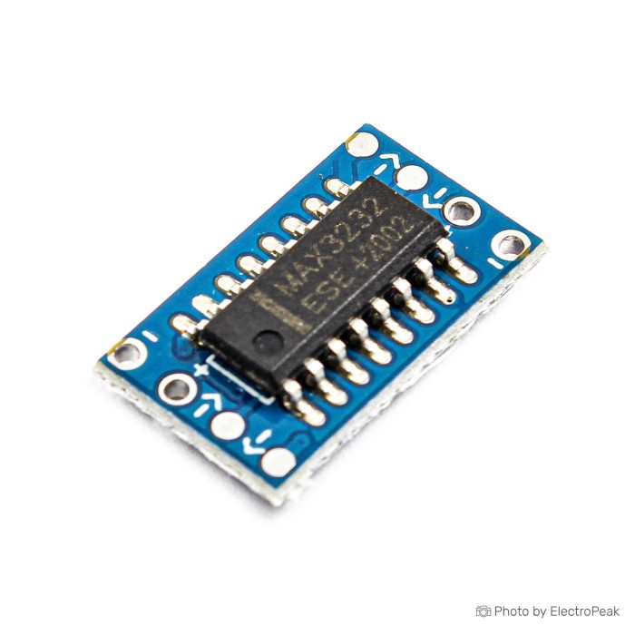
MAX3232 RS232 To TTL Mini Converter Module
$0.2400
In stock
SKU
COM-05-033
Volume discounts:
- +100 4 % $0.2300
- +1000 8 % $0.2200
- +10000 13 % $0.2100
Ships in 2-3 business days, then:
Free delivery in 12-15 days by Tracked Economic Shipping on orders over $100.
Free delivery in 7-10 days by Express Shipping on orders over $300.
More shipping info

Shop with confidence Learn More
 6 in 1 CP2102 USB to TTL/RS485/RS232 Converter Module Previous
MAX3232 RS232 to TTL Mini Converter Module Specifications
This compact MAX3232CSE-based module provides bidirectional electrical level translation between true RS-232 serial signals and TTL/UART logic levels. It operates across a 3 to 5 volts power supply range, interfacing directly with modern 3.3 V microcontrollers and traditional 5 V logic circuits. For embedded projects that need direct serial wiring to an existing RS-232 device, this small board bridges the physical signaling gap without unnecessary bulk.
At 9.4x15.9 mm, the footprint fits tight enclosures where standard connectorized boards cannot. It is intended for custom wiring to a hardware UART, not as a direct USB serial adapter or pre-wired DB9 connection. For wider serial interface options, our catalog of serial adapters and converters includes board-level transceivers and multi-interface tools.
Specifications of MAX3232 RS232 To TTL Mini Converter Module
- Dimensions: 9.4x15.9 mm
- Power Supply Voltage: 3 to 5 volts
- Main Chip: MAX3232CSE
- Data Rate: Up to 120 kilobits per second
- Normal Current Consumption: 300 microamperes
- Communication Protocol: TTL to RS232
- Voltage Compatibility: 3.3 and 5 volts
MAX3232 RS232 to TTL Mini Module Compatibility and Wiring
This module handles physical-layer voltage conversion between RS-232, which swings between positive and negative voltages, and single-ended TTL/CMOS UART signaling. It does not decode or translate serial framing, commands, USB packets, Ethernet, RS485, CAN, or SPI buses. One endpoint must be a genuine RS-232 interface, and the other must connect to a compatible microcontroller UART.
To maintain signal integrity, power the module from your microcontroller's logic supply: use 3.3 V for a 3.3 V system or 5 V for a 5 V system. Supplying 5 V while interfacing with a 3.3 V microcontroller produces TTL levels that can exceed the maximum voltage rating of MCU input pins. Always tie the module ground to the host controller ground to maintain a common electrical reference.
Cross the UART signals when wiring the module: connect the microcontroller transmit (TX) pin to the TTL input of the module, and the microcontroller receive (RX) pin to the TTL output. Inspect the physical markings on the board when it arrives to verify signal direction, as package contents do not include pre-soldered headers, a DB9 connector, or a dedicated pinout diagram. For setups that require prototyping wires, these jumper wires for TTL and power connections provide flexible lead routing.
For projects that need one tool across multiple communication standards, the CP2102 6-in-1 multi-interface converter provides USB, TTL, RS232, and RS485 serial conversion and may be a better fit than a dedicated level translator.
MAX3232 RS232 to TTL Mini Module Limits and Buyer Mistakes
A frequent mistake is buying this module to link a computer's USB port directly to a microcontroller. This board has no USB transceiver chip and cannot enumerate as a virtual COM port. It operates strictly as an analog charge-pump voltage converter between RS-232 and TTL logic lines.
The module is rated for data rates up to 120 kilobits per second. Some isolated semiconductor datasheets for the broader MAX3232 family list theoretical rates up to 250 kbps under ideal laboratory test conditions, but design baud rates around the 120 kbps specification. The listed 300 microamperes normal current consumption describes typical quiescent chip consumption; it does not represent the full dynamic power draw when driving long capacitive serial lines at high baud rates.
This generic assembly does not include galvanic isolation, defined ESD ratings, surge protection stages, or a documented operating temperature range. The PCB revision, complete schematic, and specific semiconductor foundry provenance are not stated. For setups requiring verified continuous industrial service, the documented DB9 RS232-to-TTL module specifies an operating range of -40°C to 85°C and a rated 15-meter RS-232 transmission distance.
The older MAX232 chip requires a 5 V rail to generate proper RS-232 charge-pump voltages and cannot run reliably from a 3.3 V supply. The MAX3232CSE used here addresses this by functioning down to 3 V, making it suitable for low-voltage microcontrollers. However, this board does not expose RTS/CTS flow control lines or a second serial channel; treat it strictly as a single-channel TX/RX level shifter.
MAX3232 vs MAX232 and DB9 RS232 to TTL Modules
The choice between bare level-converter modules and connectorized alternatives comes down to mechanical space and connector requirements. The table below compares common RS232-to-TTL implementations:
| Module Type | Supply Voltage | Form Factor & Termination | Best Application |
|---|---|---|---|
| MAX3232 Mini Module (This board) | 3 to 5 V | 9.4x15.9 mm solder pad breakout | Tight internal retrofits needing direct wiring |
| SP3232 Header Module | 3 to 5.5 V | 29x17x5 mm pin header interface | Breadboard prototyping without DB9 bulk |
| MAX3232 DB9 Module | 3 to 5 V | PCB with female DB9 connector and pins | Connecting directly to standard DB9 serial cables |
| SP3232 DB9 Module | 3 to 5 V | PCB with female DB9 and 6-pin interface | Connecting DTE/DCE legacy hardware via DB9 |
| MAX232 Mini Module (Generic) | 5 V only | Varies (typically solder pads or pin headers) | Legacy 5 V systems; incompatible with 3.3 V rails |
Need standard 0.1-inch spacing rather than bare pads? The compact SP3232 header module uses an alternative layout with a 3 to 5.5 V input range. For installations that connect directly to existing serial cables, the DB9-equipped MAX3232 module eliminates custom DB9 wire assembly. The DB9 SP3232 serial converter instead provides a structured 6-pin TTL connection with an integrated female port.
Cable topology remains critical whether you choose a solder-pad module or a DB9-equipped board. The data terminal equipment (DTE) or data circuit-terminating equipment (DCE) arrangement determines whether you need a straight-through connection or a null-modem crossover.
MAX3232 RS232 to TTL Mini Module Projects and Connection Parts
In embedded systems, MAX3232-family transceiver boards frequently bridge microcontrollers and legacy machinery. Maker projects use MAX3232 modules to connect an ESP32 or ESP8266 hardware UART to PiSolar inverters for home energy monitoring via ESPHome. Other common uses include reading weight telemetry from commercial RS-232 balance scales, sending control codes to legacy AV matrix switchers, and communicating with measurement equipment.
Integrating this pad-style mini module requires a compatible 3 to 5 V supply, a shared ground connection, and verified wiring to an RS-232 endpoint. When wiring directly to equipment with a classic 9-pin serial plug, a screw-terminal connector such as the DB9 terminal breakout with case provides accessible wiring terminals without hand-soldering individual D-sub pins. Where enclosure space is tight, the uncased DB9 terminal breakout serves the same wiring purpose.
Extended factory serial runs need a differential approach rather than TTL translation. In that case, the KT-C01 port-powered adapter provides RS232-to-RS485 conversion for long-distance serial networks and handles multi-drop industrial communication up to 1.2 miles.
MAX3232 RS232 to TTL Mini Module Quick Start Test
Before committing the module to a permanent circuit, perform a controlled loopback test with an external UART source or development board:
- Inspect Board Labels: Check the printed markings on both sides of the mini PCB to confirm the TTL-side and RS232-side pad designations.
- Connect Power and Ground: Apply a clean DC voltage (3.3 V or 5 V, matching your host logic) between the VCC and GND pads. Connect the host ground to the module ground.
- Perform a TTL Loopback: Before wiring the transceiver, connect the MCU TX and RX pins together directly to confirm your firmware sends and receives characters properly without hardware in between.
- Connect the TTL UART: Wire the MCU TX pin to the module TTL input pad, and the MCU RX pin to the module TTL output pad.
- Bridge the RS-232 Side: On the RS-232 side of the module, bridge the RS-232 transmit and receive pads together using a short wire jumper.
- Run the Echo Test: Transmit short ASCII strings through your microcontroller UART at a standard baud rate (such as 9600 or 115200 bps). The data should travel through the level shifter, across the RS-232 bridge, back through the receiver stage, and appear identical in your serial monitor.
This converter is a purely hardware-driven voltage-shifting circuit, so it requires no software drivers, register initialization, or firmware libraries. If received data is garbled or does not return, confirm that the serial terminal matches your firmware's parity, data bits, and stop bits, then verify that the module is powered from the appropriate logic rail. When troubleshooting from a PC without built-in serial ports, a dedicated USB-to-DB9 RS232 adapter can serve as a known-good reference receiver during testing.
MAX3232 RS232 to TTL Mini Module FAQ and Buying Checklist
Is the MAX3232 RS232 to TTL Mini Converter Module a USB-to-serial adapter?
No. This module has no USB interface and converts electrical signals between true RS-232 voltage levels and TTL/CMOS UART signals. For a configurable bridge with USB connectivity alongside legacy standards, consider the CP2102 6-in-1 multi-interface converter instead.
Can I use this MAX3232 module with an ESP32?
Yes, the module supports 3.3 V operation. Power it from the ESP32 3.3 V rail, connect a shared ground, and route the module TTL lines to your designated hardware UART pins, such as Serial1 or Serial2, defined in your code.
Can I use this MAX3232 module with a 5 V Arduino?
Yes, the module is compatible with 5 V systems within its listed 3 to 5 volts supply range. Supply the VCC pin with 5 V from the Arduino board so the module output logic levels properly match the 5 V ATmega UART thresholds.
Does it automatically work with both 3.3 V and 5 V devices at the same time?
No. It does not perform simultaneous dual-rail voltage translation. The TTL side operates at the single voltage supplied to its VCC pin; do not power it with 5 V and connect the TTL lines directly to a 3.3 V microcontroller.
Is 120 kbps the maximum speed?
Yes, 120 kilobits per second is the module's rated data limit. Although some individual transceiver ICs support faster rates, designs using this board should operate at or below 120 kbps to maintain reliable edge transitions.
Will this plug directly into a DB9 serial port?
No, this is a bare mini PCB with solder pads and does not include a DB9 connector or cable. For projects connecting directly to equipment with a D-sub port, the RS232 to TTL module with DB9 offers an integrated connectorized layout, or you can add a standalone DB9 terminal breakout.
Why do I get no data or garbled characters with a MAX3232 module?
Garbled output or missing transmissions are most often caused by uncrossed TX/RX connections, missing common ground references, baud rate mismatches, or inverted DTE/DCE cable connections that require a null-modem swap.
Does this board support RTS/CTS hardware flow control or two serial ports?
No, this mini board only breaks out the primary TX and RX channels. It does not provide access to secondary transceiver channels or RTS/CTS hardware handshaking lines.
Is this module isolated or rated for industrial and long-cable use?
No, the module does not include galvanic isolation, transient voltage suppression diodes, or industrial surge certifications. Select an isolated serial interface for noisy environments or long field wiring where ground loops may occur.
Purchase Decision Summary
- Ideal for: Makers looking to add a very small, low-cost RS-232 level shifter to a 3.3 V ESP32 or 5 V Arduino project with direct custom wiring.
- Maybe for: Embedded equipment retrofits and robotics with cramped internals where DB9 connectors are physically too large.
- Avoid if: You need a direct computer USB connection, require a pre-mounted DB9 connector, need hardware flow control, or require galvanic isolation and industrial surge ratings.
Buying Checklist
- Confirm your target device communicates via true RS-232 voltage levels, not TTL, USB, or RS485.
- Verify that your host microcontroller uses a 3.3 V or 5 V asynchronous UART.
- Confirm that your required serial transmission rate does not exceed 120 kbps.
- Ensure you have soldering tools and wiring available to connect to the 9.4x15.9 mm board pads.
- Determine whether your RS-232 peripheral requires a DB9 terminal adapter or a null-modem crossover.
- Check that your project does not require RTS/CTS hardware handshaking lines.
- Verify that your installation environment does not require optical isolation or certified industrial surge suppression.
| Platform | Arduino Uno, Raspberry Pi 3, Raspberry Pi 4, Raspberry Pi 5 |
|---|---|
| Interface Type | UART, RS232 |
| Operating Voltage (V) | 3V to 5V |
| Operating Current (mA) | 0.3 mA |
| Operating Temp (°C) | 0 to 70 |
| Dimensions (mm) | 9.4x15.9 mm |
| Data transmission rate | 120 kbps |
| Standard | RS232 |
| Voltage Levels | 3.3V, 5V |
| Chipset | MAX3232CSE |
| Direction | Bidirectional |
Write Your Own Review

Please complete your information below to login.
Sign In
Create New Account