
Product added to cart

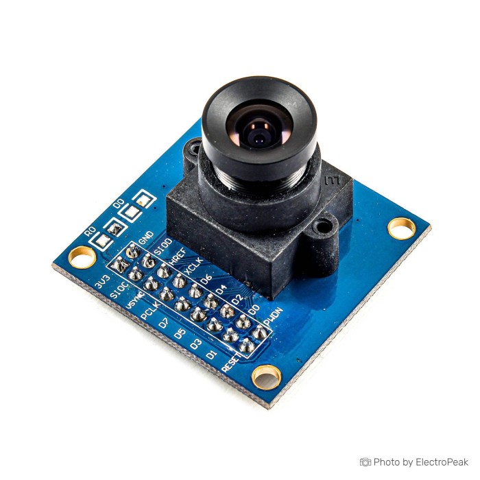
VGA OV7670 Camera Module 640X480
$1.3300
In stock
SKU
CAM-01-004
Volume discounts:
- +50 4 % $1.2800
- +100 5 % $1.2600
- +300 8 % $1.2300
- +500 9 % $1.2100
- +1000 11 % $1.1900
Product Variations:


Ships in 2-3 business days, then:
Free delivery in 12-15 days by Tracked Economic Shipping on orders over $100.
Free delivery in 7-10 days by Express Shipping on orders over $300.
More shipping info

Shop with confidence Learn More
 Waveshare 5MP Camera Board - OV5640 Sensor, Fisheye Lens Previous
OV7670 Camera Module Review: VGA Parallel Camera Basics
The OV7670 is a VGA CMOS camera module for low-level embedded vision and digital signal-processing experiments. Unlike an automated plug-and-play webcam, this sensor exposes a direct parallel pixel interface alongside a two-wire serial configuration bus. Capturing an image requires an embedded host that can supply a master clock, configure registers over an I2C-compatible bus, and receive byte-wide parallel data on high-speed hardware pins.
This module suits engineers, students, and makers working with microcontrollers, DSPs, or FPGAs who need direct access to raw RGB, processed RGB, or YUV pixel streams without intermediate compression layers. It does not stream video over USB, Wi-Fi, or simple serial UART, so it is not suitable for quick webcam setups or low-pin-count microcontrollers without parallel capture hardware. For projects that prefer standard pin headers or specific socket packaging, the OV7670 camera module with connector provides the same sensor architecture under an alternate listing. Browse related hardware in our embedded image-processing modules catalog.
Specifications of VGA OV7670 Camera Module 640X480
- Image sensor: OV7670 image sensor
- Photographic array: 640X480
- Image rate: VGA image up to 30 frames / sec
- IO voltage: 2.5V to 3.0V (internal LDO for nuclear power 1.8V)
- Power operation: 60mW/15fpsVGAYUV
- Sleep: <20μA
- Control interface: Standard SCCB interface compatible with I2C interface
- Output formats: RawRGB, RGB (GRB4: 2:2, RGB565/555/444), YUV (4:2:2) and YCbCr (4:2:2) output format
- Output sizes: Supports VGA, CIF, and from a variety of sizes CIF to 40x30
- Sub-sampling: VarioPixel sub-sampling mode
- Image controls: automatic exposure control, automatic gain control, automatic white balance, automatic elimination of light stripes, automatic black level calibration
- Image-quality controls: color saturation, hue, gamma, sharpness ANTI_BLOOM
- Image processing: ISP has a compensation function to eliminate noise and dead pixels
- Scaling: Support for image scaling
- Optical compensation: Compensation for loss of optical lens
- Flicker detection: 50/60Hz automatic detection
- Saturation adjustment: Saturation automatically adjust (UV adjustment)
- Edge enhancement: Automatically adjust edge enhancement
- Noise reduction: Noise Reduction automatically adjust
- Frame options: output the entire frame, sub-sampling, taking a variety of windows
OV7670 Camera Module Specifications Explained
Evaluating an embedded camera module means considering how the raw sensor capabilities translate into processing, memory, and timing demands on the host processor.
| Specification | Documented Value | Why It Matters |
|---|---|---|
| Active Resolution | 640X480 (VGA / 0.3 MP) | Supplies enough spatial resolution for color classification, edge detection, and low-resolution display previews without creating unmanageable data payloads. It is not intended for detailed photographic or high-definition recording tasks. |
| Output Formats | RawRGB, RGB565/555/444, GRB 4:2:2, YUV/YCbCr 4:2:2 | Allows direct streaming to standard color LCDs (via RGB565) or luminance/chrominance vision pipelines (via YUV). Hardware JPEG compression is not included, meaning the host MCU must ingest and store uncompressed pixels directly. |
| Frame Scaling & Windowing | VGA, CIF, down to 40x30; VarioPixel sub-sampling | Host memory bandwidth can be preserved by cropping or sub-sampling the sensor output inside the camera rather than discarding data after receiving it over parallel GPIOs. |
| Sensor Image Rate | VGA image up to 30 frames / sec | Represents the internal timing capability of the sensor array. Total end-to-end throughput depends on host bus read speeds, memory bandwidth, clock synthesis, and whether frames are buffered in RAM or pushed immediately to a display. |
| Onboard Image Processing | AEC, AGC, AWB, noise reduction, gamma, edge enhancement | An integrated image signal processor corrects optical lens falloff, removes dead pixels, and stabilizes exposure dynamically, saving the host microcontroller from executing image-correction routines in software. |
| Power Dissipation | 60mW/15fpsVGAYUV; Sleep <20μA | Specifies low sensor-level draw during operation and sleep. Actual module consumption will vary depending on external support components, pull-up resistors, and any linear regulator current present on the breakout board. |
For designs that require higher resolution or integrated compression to offload frame buffering, the header-equipped OV2640 module with hardware JPEG compression provides a 2-megapixel array and direct 3.3V LVTTL signaling on a 20-pin header.
OV7670 Camera Module Compatibility and Wiring Requirements
Operating the OV7670 involves two distinct interfaces. The Serial Camera Control Bus (SCCB) uses I2C-compatible clock (SIOC) and data (SIOD) lines to write and read configuration registers. Image transfer does not travel over these control pins. Instead, pixels are transmitted over an 8-bit parallel bus (D0 through D7), synchronized by three high-speed timing lines: Pixel Clock (PCLK), Horizontal Reference (HREF), and Vertical Sync (VSYNC).
Physical board revisions vary across generic manufacturing runs, and specific pinouts, onboard pull-up configurations, header pitches, and oscillator presence are not supplied for this exact board. Verify silkscreen markings and circuit traces on the delivered unit before wiring power or data lines.
| Signal Group | Pins / Lines | Host Requirement |
|---|---|---|
| Register Control | SIOC (SCL), SIOD (SDA) | Standard I2C or bit-banged SCCB interface at 3.3V logic levels to configure operational modes. |
| Data Bus | D0, D1, D2, D3, D4, D5, D6, D7 | Eight consecutive or easily masked high-speed digital input pins, ideally routed to a DMA-capable parallel peripheral. |
| Sync & Clocking | PCLK, HREF, VSYNC, XCLK | PCLK, HREF, and VSYNC serve as host capture interrupts/strobes. XCLK requires an external master clock input (typically 8 to 24 MHz) unless the delivered module integrates an active oscillator. |
| Control & Power | RESET, PWDN, VCC, GND | RESET resets register values; PWDN controls low-power standby. Listed IO voltage is 2.5V to 3.0V (internal LDO for nuclear power 1.8V). 5V input and 5V logic tolerance are not documented. |
Host controller choice dictates success. 32-bit platforms such as the STM32 family, especially models equipped with a Digital Camera Interface / DCMI peripheral, custom ESP32 firmware using parallel DMA I2S engines, CircuitPython boards with dedicated parallel capture support, and embedded Linux boards with compatible device trees are capable hosts. Standard 8-bit microcontrollers such as the Arduino Uno or Nano lack both the clock speed and RAM needed to ingest full-resolution frames directly. Stock ESP32 frameworks such as ESPHome or the standard ESP32 CameraWebServer example target 2MP sensors rather than this module.
A reliable test-bench setup for the extensive signal bus requires multiple secure jumpers. A jumper wire kit for parallel camera wiring helps maintain solid connections across the data, clock, and control pins. Projects built around standard camera sockets on ESP32 development hardware are better served by the 2MP OV2640 ribbon-camera module, which offers direct connector compatibility with lower wiring complexity.
OV7670 Camera Module Limitations and Common Mistakes
The most frequent OV7670 integration failure is underestimating the memory math. A single uncompressed 640x480 frame in 16-bit RGB565 format requires 614,400 bytes (over 600 KB) of contiguous buffer memory. Microcontrollers with 2 KB to 32 KB of internal SRAM cannot store a full VGA frame without dropping to smaller window sizes, such as QQVGA 160x120 or 40x30, or processing individual scanlines on the fly.
Onboard buffering is another major consideration. The presence of an onboard FIFO buffer memory chip, such as an AL422B, is not documented for this board. Without a FIFO IC to store frames on the camera board itself, the host processor must capture incoming pixel bytes in real time at the sensor's pixel clock frequency. Missing a single clock pulse shifts downstream pixel boundaries and results in rolling or diagonal image corruption.
Keep these common integration pitfalls in mind:
- Assuming 5V safety: The listed IO voltage is 2.5V to 3.0V. Applying 5V power or 5V logic signals from legacy boards without verified level shifting risks damaging the camera module.
- Missing the master clock (XCLK): The OV7670 internal state machine will not run, and the SCCB bus will not acknowledge commands, unless a valid master clock signal is supplied or an onboard oscillator is active.
- Mismatched byte ordering: RGB565 requires two bytes per pixel. Inverting the byte sequence swaps red and blue color channels, producing green-tinted or inverted imagery on local displays.
- Incomplete pin labeling: Do not rely on pinout diagrams from third-party OV7670 tutorials without verifying the silkscreen on your physical PCB, as generic revisions frequently swap control and data pin positions.
- Undocumented optical geometry: Precise lens field of view, focal length, mounting thread dimensions, and infrared cut-filter specifications are not published for this module.
For bench testing, a prototype assembled on an 830-point breadboard lets you probe sync lines and organize signal groups cleanly. Systems with a dedicated 24-pin ribbon receptacle that require higher resolution can use the 3MP 24-pin camera module, a direct alternative with native support in modern embedded vision frameworks.
OV7670 Camera Module vs OV2640 and FIFO Alternatives
The right embedded camera depends on whether you need raw pixel evaluation, compact ribbon connectors, or host-managed compression.
| Feature | VGA OV7670 Module | OV2640 20-Pin Header Module | OV2640 Ribbon Module | OV3660 24-Pin Module | OV7670 + AL422B FIFO (Reference) |
|---|---|---|---|---|---|
| Array Resolution | 640x480 (0.3 MP) | 1600x1200 (2 MP) | 1632x1232 (2 MP) | 2048x1536 (3 MP) | 640x480 (0.3 MP) |
| Hardware JPEG | No | Yes | Yes | Yes | No |
| Physical Interface | Parallel breakout pins | 20-pin 2.54mm header | Flexible ribbon connector | 24-pin FPC ribbon | Dual-row breakout pins |
| Output Formats | RawRGB, RGB, YUV, YCbCr | JPEG, RGB565, YUV | JPEG, RGB565, YUV | JPEG, RGB565, YUV, RAW | RawRGB, RGB, YUV, YCbCr |
| Frame Buffer IC | Not documented | No (relies on host/JPEG) | No (relies on host/JPEG) | No (relies on host/JPEG) | Yes (AL422B 384 KB buffer) |
| Primary Use Case | VGA raw/RGB learning and low-level DSP | Breadboard DSP, FPGA, and STM32 builds | Compact ESP32-CAM replacements | High-resolution upgrades for 24-pin sockets | Slow microcontrollers capturing VGA frames |
In low-memory architectures, an OV7670 FIFO camera module decouples sensor readout from host clock constraints by dumping the frame into an integrated AL422B buffer chip. This allows an 8-bit MCU to read bytes at leisure. Because FIFO presence is not documented on this standard module, the host must capture pixels in real time. Historical Arducam OV7670 modules introduced proprietary Arduino shields to handle this timing, but those software libraries do not map directly to standalone generic modules.
For higher clarity without manual timing synchronization, the header-equipped OV2640 module compresses frames directly to JPEG, drastically reducing RAM demands. Compact mobile housings can use the standard OV2640 ribbon-camera option, while the 3MP 24-pin ESP32-CAM-compatible camera option matches modern development board sockets directly.
OV7670 Camera Module First-Image Setup Check
This board does not operate through USB, so no CH340 or serial bridge driver installation applies. Getting a first valid image requires a methodical hardware and signal check.
- Inspect the PCB: Examine both sides of the module. Confirm the OV7670 sensor marking on the optical package, record the silkscreen labels beside each header pin, and check whether an auxiliary crystal oscillator or FIFO IC is present.
- Establish Safe Power and Logic: Connect ground and a regulated supply matching your module's markings within the 2.5V to 3.0V specification. Verify that all host GPIO logic levels conform to the camera's input limits.
- Provide Master Clocking: If your module lacks an onboard crystal, configure a timer or PWM output on your host MCU to supply an 8 to 24 MHz square wave to the camera's XCLK pin.
- Validate SCCB Communication: Connect the SIOC and SIOD lines with appropriate pull-up resistors. Run an I2C scan to confirm the camera acknowledges its bus address, and read the product ID register (0x0A / 0x0B) to verify two-way communication before touching parallel lines.
- Wire the Parallel Bus: Route D0–D7 to a single input port on your microcontroller, and tie PCLK, HREF, and VSYNC to interrupt-capable or DMA-trigger pins using secure leads from a jumper wire kit.
- Test with Reduced Windowing: Configure the sensor for a small resolution, such as QQVGA 160x120, and RGB565 output. Verify that the total number of received PCLK pulses per frame matches your expected byte count before trying full VGA capture.
- Tune Pixel Alignment: If the captured preview shows diagonal banding, inverted colors, or shifted scanlines, adjust your controller's PCLK sampling edge (rising vs. falling), verify the RGB byte order, and confirm your HREF line state handling.
OV7670 Camera Module FAQ and Buying Checklist
Does the OV7670 camera module send images over I2C?
No. The module does not transmit image data across I2C. The SCCB interface, which is I2C-compatible, is used exclusively to read and write internal configuration registers, while image pixels are clocked out over a separate 8-bit parallel bus (D0–D7) governed by PCLK, HREF, and VSYNC timing signals.
Will this OV7670 camera module work with Arduino Uno or Nano?
Direct full-resolution VGA capture is not practical on an Arduino Uno or Nano. An uncompressed 640x480 RGB565 frame requires 614,400 bytes, which massively exceeds the 2 KB of SRAM available on an ATmega328P. Basic low-resolution or scanline-streaming experiments are possible with advanced code, but standard photographic workflows will fail due to memory limits.
Does this OV7670 camera module work with ESP32 CameraWebServer or ESPHome?
No. Standard ESP32 CameraWebServer examples and ESPHome configurations are preconfigured for 2MP sensors such as the OV2640 and do not support this module out of the box. Running an OV7670 on an ESP32 requires custom drivers, custom pin mappings, and manual DMA configuration. For an out-of-the-box wireless workflow, consider an ESP32-CAM board with OV2640 instead.
Does this module include a FIFO buffer?
FIFO status is not documented for this board. Unless an AL422B FIFO chip is verified on the physical PCB, assume the module requires direct real-time parallel capture by the host controller.
Can this OV7670 camera module run from 5 V?
No. The documented IO voltage is 2.5V to 3.0V. Direct 5V power or 5V logic inputs are not documented as safe and can permanently damage the camera sensor unless an onboard regulator and level shifters are confirmed on your PCB.
Does the OV7670 output JPEG images?
No. The OV7670 does not feature hardware JPEG compression. It outputs uncompressed formats including RawRGB, RGB565/555/444, and YUV/YCbCr 4:2:2. If you need compressed JPEG images for lightweight storage or web transmission, choose an OV2640 module with 20-pin header.
Is VGA 30 fps guaranteed in my project?
No. The "up to 30 frames / sec" rating describes the sensor's maximum internal output capability. The frame rate achieved in an actual build is limited by your host controller's GPIO acquisition rate, DMA bandwidth, processor frequency, and storage or display transfer speeds.
Why does an OV7670 image look scrambled or have incorrect colors?
Scrambled images are almost always caused by timing or data-order mismatches. Check that D0 through D7 are wired in the correct order, toggle host sampling between the rising and falling edge of PCLK, verify proper byte alignment for 16-bit color, confirm stable master clock (XCLK) input, and verify common ground between the camera and host.
Purchase Decision Summary
- Ideal for: Experienced embedded developers, students, and engineers using STM32, ESP32 (custom drivers), or FPGA platforms who want to explore low-level parallel camera timing, register manipulation, and raw/RGB/YUV pixel processing.
- Maybe for: Low-resolution vision experiments or small display previews (such as 160x120) on 32-bit microcontrollers with limited RAM, provided you can handle parallel GPIO capture and external clock generation.
- Consider another option if: You need simple plug-and-play USB operation, standard Arduino Uno compatibility, wireless camera web streaming, hardware JPEG compression, or drop-in ESPHome integration.
For standalone IoT vision projects that require ready-made streaming firmware and wireless connectivity, the ESP32-CAM board with OV2640 integrates Wi-Fi, Bluetooth, and microSD logging on a single board. If higher resolution and simpler USB flashing are required, the 5MP ESP32 camera board with Micro USB provides a complete development environment. Browse additional imaging hardware in our image-processing modules and camera hardware category.
Buying Checklist
- Host controller has at least 10 to 12 available digital pins capable of high-speed capture (8 data lines plus sync and control).
- Host architecture provides sufficient RAM for your target resolution (614 KB for full VGA RGB565) or supports scanline streaming.
- Hardware setup includes a stable 2.5V to 3.0V power source and 3.3V-compatible logic levels.
- You have a method to supply an 8 to 24 MHz master clock (XCLK) if the received PCB does not integrate an oscillator.
- The project pipeline supports raw RGB or YUV data and does not depend on sensor-level JPEG compression.
- Software architecture can use custom register configuration rather than standard stock ESP32-CAM firmware.
- Breadboard jumpers and test equipment (such as a logic analyzer) are available to verify signal timing.
| Interface Type | I2C,Parallel |
|---|---|
| Operating Voltage (V) | 1.8V (Core), 2.5V-3.0V (I/O) |
| Operating Current (mA) | 60mW |
| Operating Temp (°C) | -30 to 70 |
| Output Type | Digital |
| Resolution | 640X480 |
| Pixel Resolution | VGA (640x480) |
| Field of view angle (degrees) | 25° |
| Chipset | OV7670 |
| Sensor Type | CMOS |
| Output Interface | Digital |
| Application | Processing systems,Monitoring,Robotics |
| Dynamic Range | 52 dB |
| Pixel Size | 3.6x3.6μm |
Write Your Own Review

Please complete your information below to login.
Sign In
Create New Account