
Product added to cart

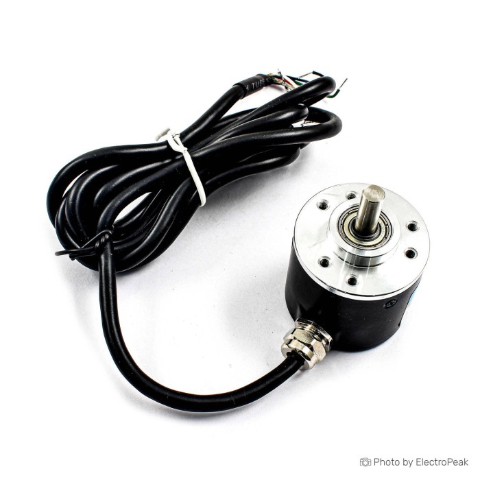
360PPR 2-Phase Optical Incremental Rotary Encoder
$11.2500
In stock
SKU
SEN-23-001
Volume discounts:
- +25 5 % $10.7200
- +50 7 % $10.4600
- +100 9 % $10.1900
- +300 12 % $9.9300
- +500 14 % $9.6700
Ships in 2-3 business days, then:
Free delivery in 12-15 days by Tracked Economic Shipping on orders over $100.
Free delivery in 7-10 days by Express Shipping on orders over $300.
More shipping info

Shop with confidence Learn More
 KY-040 Rotary Encoder Module with Push Switch Previous
360PPR Optical Incremental Rotary Encoder Review
This 360PPR optical incremental rotary encoder is an AB quadrature shaft sensor for tracking relative speed, direction, and displacement in microcontrollers, PLCs, robotics, and small automation setups. With a 38 mm outer diameter and 6 mm solid shaft, it uses an internal disc to produce two out-of-phase pulse trains as the shaft turns. It suits projects that monitor continuous rotation or relative movement where a home switch or startup calibration is available. It is not intended for setups requiring absolute position at boot, a dedicated index pulse, or verified environmental ratings.
Before purchasing, review the broader rotary encoder category to confirm whether an incremental shaft encoder or an absolute position sensor suits your mechanical assembly.
Specifications of E38S6G5 360PPR 2-Phase Optical Incremental Rotary Encoder
- Model: HN3806-AB
- Pulse Number: 360
- Power source: DC 5-24V
- Shaft diameter: 6mm
- Outer diameter: 38mm
- Output: AB 2phase output rectangular orthogonal pulse circuit, the output for the NPN open-collector output type
- Maximum mechanical speed: 5000 R / min
- Response frequency: 30KHz
- Cable length: 2 meter
- Connection: Green = A phase, white = B phase, red = Vcc, black = GND
360PPR Optical Encoder Wiring and Compatibility
This 2-phase encoder provides relative rotational feedback on two channels, Phase A and Phase B, through NPN open-collector outputs. In an open-collector stage, the encoder’s internal transistors pull the output line to ground but do not drive it high. Both signal lines therefore need external pull-up resistors or verified receiver pull-ups. Connecting Phase A or Phase B directly to VCC without a current-limiting pull-up will burn the output triode inside the unit.
NPN open-collector outputs allow the encoder supply voltage and output logic voltage to be selected independently. You can power the encoder from a 12 V or 24 V rail for industrial supply lines while connecting the Phase A and Phase B pull-up resistors to a 3.3 V or 5 V rail on an Arduino or ESP32. Never connect the pull-up resistors to 12 V or 24 V when using low-voltage microcontroller inputs. In non-isolated installations, the encoder ground (black) must share a common ground reference with the receiving logic.
The encoder produces simple digital pulse trains, so it needs no USB driver or vendor-specific library. The receiving board detects state changes or edge transitions. For initial prototyping, a temporary wiring for signal testing kit helps connect the flying leads to standard 2.54 mm breadboard rails. For a step-by-step connection walkthrough, see our guide on photoelectric encoder Arduino wiring.
For a miniature mechanism with a 3 mm motor shaft, where an enclosed 38 mm housing is too bulky, consider a fixed-5V optical-disc approach for small shafts as a lightweight alternative.
| Parameter / Interface | Specification / Requirement | Integration Notes |
|---|---|---|
| Output Type | AB 2-phase NPN open collector | Requires pull-ups on both A and B channels; never short directly to VCC. |
| Supply Voltage | DC 5-24V | Independent of signal logic levels; power from any stable DC rail in this range. |
| Logic Levels | Determined by pull-up voltage | Safe for 3.3 V or 5 V MCU inputs when pulled up to the respective controller rail. |
| Grounding | Common signal ground | Black wire must tie to controller ground in non-isolated systems. |
| Decoding Support | Quadrature (x1, x2, x4) | Requires GPIO with external interrupts, hardware timers, or dedicated counter ICs. |
| Drivers | None | Pure hardware pulse train; no software drivers required. |
360PPR Encoder Specifications Explained
Physical rotation becomes digital transitions in the controller, so these specifications matter when matching this 360PPR optical encoder to your processing hardware.
| Published Specification | Value | Why It Matters to Your Build |
|---|---|---|
| Pulse Number | 360 PPR | Defines physical lines on the internal disc. In software, reading single edges (x1) yields 360 counts per revolution (1.0° resolution). Decoding both edges of one channel (x2) yields 720 counts (0.5°). Decoding all rising and falling edges across both channels (x4) yields 1,440 counts per revolution (0.25°). |
| Response Frequency | 30KHz | The maximum frequency the internal optical pickup and switching transistor can toggle cleanly on a single channel. At 360 PPR, rotating at 5,000 rpm generates 30 kHz on Phase A ((360 × 5000) / 60 = 30,000 Hz). |
| Maximum Mechanical Speed | 5000 R / min | The upper limit for the physical shaft and internal optical reading. Running at 5,000 rpm with x4 quadrature decoding produces 120,000 edge transitions per second, requiring hardware timers or efficient interrupt handlers. |
| Shaft & Body Dimensions | 6 mm shaft, 38 mm outer diameter | The physical form factor for mounting brackets and couplings. Note that shaft length and face mounting hole patterns are not published in the baseline specifications and must be verified on the unit. |
| Cable Length | 2 meter | Provides sufficient lead length for machinery frames without immediate inline splicing. Longer runs increase line capacitance, which may necessitate lower pull-up resistor values. |
For small geared motors rather than an external shaft assembly, a dedicated motor-tail Hall encoder for JGB37/JGA25 motors mounts directly to the motor armature instead of using a separate 38 mm body.
360PPR Optical Encoder Limitations
This incremental encoder has defined limits that affect speed and relative-positioning system design:
- No Absolute Position or Index Channel: The wiring documents only four conductors: Phase A, Phase B, Vcc, and GND. There is no documented Z (index) channel to provide a single zero pulse per revolution. All position data is lost when power is off; systems requiring an exact origin must use an external home limit switch or optical flag.
- High Interrupt Overhead: A 360 PPR unit produces 1,440 edges per revolution under x4 decoding. At moderate to high speeds, this can easily swamp an 8-bit microcontroller when handled purely through basic software interrupts. Dedicated hardware quadrature encoder interfaces, such as those found on the ESP32, STM32, or dedicated counter chips, are strongly recommended for high-RPM operation.
- Supply Voltage Headroom: Although the specification lists DC 5-24V, community testing across related E38S6-family units indicates that internal regulator dropouts can occasionally cause erratic operation when supplied with exactly 5.0 V under heavy line drop. In a strictly 5 V environment, bench-test your unit to verify clean switching before final integration, or power the encoder from 9–24 V while pulling the signal lines to 5 V.
- Unverified Environmental and Mechanical Ratings: Specific IP ingress protection, shock ratings, bearing life limits, and shaft load capacities are not published. Do not deploy it in submerged, high-washdown, or extreme-vibration environments without supplemental protective housings.
- Family Documentation Variances: Across generic 3806/38S6 series models, factory wire colors occasionally switch Phase A and Phase B. Always bench-verify your unit’s directional rotation before completing permanent field wiring.
Where immediate true-angle data is required across 360 degrees without homing cycles or moving cables, an adjacent non-contact sensor such as the non-contact magnetic angle measurement module provides absolute 12-bit position through I2C or analog outputs.
360PPR Optical Encoder Uses and Alternatives
This optical shaft encoder suits continuous rotational tracking where a mechanical shaft can be coupled directly or through timing belts. Common implementations include:
- Motor Speed & RPM Feedback: Monitor spindle, motor, or wheel speeds through pulse-frequency measurement.
- Linear Measurement: Track conveyor belts, roller feeds, or lead-screw travel by translating shaft revolutions into linear distance.
- Actuator & Joint Tracking: Provide relative angular-position feedback in robotic arms or automated turntables paired with a physical home switch.
- Heavy-Duty Control Interfaces: Use it as a robust, smooth, un-detented input dial or simulator control wheel, such as DIY racing wheel inputs demonstrated in related family designs.
Connecting this unit to a drive mechanism requires a properly sized mechanical coupler. Although 3D printer hardware lines offer related shaft-coupling formats, make sure any coupler you purchase has an exact 6 mm bore on the encoder side to prevent shaft runout.
Do not confuse this shaft sensor with user-interface knobs. For microcontroller menu navigation or setting digital parameters on a front panel, a 38 mm shaft encoder is unnecessarily large and lacks a push-button. Choose a manual menu-control encoder module or a panel-mount control knob designed for low-speed human input. For basic interface code for user dials, see our guide on rotary encoder Arduino interface basics.
360PPR Encoder Setup Check
Verify the encoder on the bench before permanently bolting it into machinery:
- Examine the Wiring Label: Check the label on the encoder body to confirm that the color code matches the specification: Red = Vcc, Black = GND, Green = Phase A, White = Phase B.
- Mechanical Positioning: Mount the encoder loosely or secure the body so the 6 mm shaft spins freely without binding or radial load.
- Connect Power: Connect Black to system DC Ground. Connect Red to your power source (DC 5–24 V). If using an external supply separate from your microcontroller, join their grounds together.
- Install Pull-Up Resistors: Place a resistor (1 kΩ to 10 kΩ) between Phase A (Green) and your receiver’s logic rail (e.g., 3.3 V or 5 V). Place an identical resistor between Phase B (White) and the same logic rail. Do not connect these to the encoder’s 12 V/24 V supply when using a low-voltage controller.
- Verify Transitions: Connect Phase A and Phase B to an oscilloscope, logic analyzer, or interrupt-enabled microcontroller pins. Rotate the shaft slowly by hand. You should see clean square waves toggling between 0 V and your logic rail.
- Check Phase Relationship: Turning the shaft clockwise should show Phase A leading Phase B, or vice versa. Reverse the direction to confirm that the phase lead flips. If software direction reads backward, swap the Phase A and Phase B inputs.
- Set Decoding Scheme: Configure your software to count single edges (360 counts/rev) or all edges (1,440 counts/rev), based on your application's resolution and processing budget.
For a complete tutorial on pulse reading and code structuring, consult our full Arduino photoelectric encoder guide.
360PPR Rotary Encoder Accessories and Buying Checklist
This encoder requires complementary interface and mounting components:
Required Hardware (Not Included)
- Pull-Up Resistors: Two resistors, typically 1 kΩ to 4.7 kΩ for 3.3 V/5 V logic, or confirmed active internal pull-up inputs on the controller.
- DC Power Supply: A filtered 5 V to 24 V DC power rail.
- Shaft Coupler: A 6 mm flexible or rigid coupling matched to your driving shaft diameter. Listings such as related flexible shaft couplings use 5 mm bores and will not fit this 6 mm shaft.
- Receiving Controller: A microcontroller GPIO with hardware interrupts, a PLC digital counter card, or a hardware quadrature decoder.
Recommended Additions
- Prototyping Leads: A temporary wiring for signal testing set for bench evaluation.
- Home/Limit Sensor: A microswitch or optical interrupter when your mechanism requires an absolute reference datum at startup.
- Mounting Bracket: Custom fabrication or a matched plate. Although items such as related mounting hardware exist for motors, they are not tailored to this encoder's mounting pattern and should not be assumed to fit.
If this mechanical format does not suit your enclosure, you can browse rotary encoder types to assess other form factors.
Purchase Decision Summary
- Ideal for: DIY machinery, robotics, test benches, and industrial automation where a 6 mm shaft can be coupled to track continuous relative speed, distance, or direction into an MCU or PLC.
- Maybe for: Systems operating near 5,000 rpm or using 5 V-only single rails, provided the controller can handle 120 kHz edge rates and a bench test confirms clean 5 V operation.
- Consider another option if: You need true absolute angle without homing cycles, need an index (Z) pulse, require certified IP washdown protection, or simply need a small rotary knob for a digital display panel.
Buying Checklist
- [ ] My drive mechanism connects to a 6 mm smooth round shaft.
- [ ] My enclosure accommodates a 38 mm diameter body.
- [ ] I have two pull-up resistors available to pull Phase A and Phase B to my microcontroller's logic level.
- [ ] I have verified that my pull-up voltage matches my controller input limits (e.g., 3.3 V or 5 V), even if the encoder is powered from 12 V or 24 V.
- [ ] My microcontroller has sufficient interrupt bandwidth or hardware quadrature decoding for my planned RPM.
- [ ] I have planned an external home switch if my mechanism needs an exact reference point on boot.
- [ ] I have not ordered 5 mm couplers expecting them to fit this 6 mm shaft.
360PPR Rotary Encoder FAQ
Is this a 360PPR absolute encoder?
No. This is an incremental optical encoder that outputs continuous quadrature pulses to indicate relative motion and direction, but it does not store or output a fixed angular coordinate when power is applied.
Does 360 PPR mean my software always reads 360 counts per revolution?
No. The count depends entirely on your microcontroller’s quadrature decoding configuration. In x1 mode, reading one edge of one channel, it reads 360 counts; in x2 mode, reading both edges of one channel, it reads 720 counts; and in x4 mode, reading all rising and falling edges across both channels, it produces 1,440 counts per revolution.
Can I connect this 360PPR optical encoder to Arduino or ESP32 inputs?
Yes, provided you connect pull-up resistors between the signal lines and the microcontroller's logic voltage rail: 5 V for standard Arduino and 3.3 V for ESP32. Because the encoder outputs are NPN open collector, they pull only to ground and will not expose your microcontroller to higher encoder supply voltages as long as the pull-ups are tied to the MCU rail. For software examples, see our Arduino rotary encoder guide.
Do I need pull-up resistors on Phase A and Phase B?
Yes. Pull-up resistors are required on both channels. Without pull-up paths, an NPN open-collector output floats when not actively pulling low, resulting in unreadable or erratic signals. Never connect Phase A or Phase B directly to VCC without a resistor, as this will destroy the output transistors.
Can I power this encoder from a 5 V Arduino supply?
The published supply specification is DC 5-24V, so it can be connected to a 5 V supply. However, internal regulator variations in this encoder family can sometimes require slightly higher supply headroom, around 6.5 V to 7 V, for reliable operation. Bench-test your unit when running on a strict 5.0 V rail, or power it from a 9 V to 12 V adapter while keeping pull-ups tied to 5 V.
If I power the encoder from 12 V, are the Phase A and Phase B outputs also 12 V?
Only if you mistakenly connect the pull-up resistors to the 12 V rail. In an NPN open-collector circuit, the output high level is determined entirely by the pull-up-resistor connection, allowing you to power the unit at 12 V while safely pulling the signal outputs to 3.3 V or 5 V.
Does this encoder have a Z or index output?
No. This model has only four wires: Phase A (green), Phase B (white), Vcc (red), and GND (black). It does not provide an index (Z phase) channel for single-pulse zero-referencing.
Which wire is Phase A and which wire is Phase B?
The manufacturer specification assigns Green to Phase A, White to Phase B, Red to Vcc, and Black to GND. Because wire-color conventions can vary across production batches of generic 3806 models, check the label on your specific unit and verify rotation direction in software before final mounting.
Will it work at 5,000 rpm?
Mechanically, the unit is rated up to 5,000 rpm, and its 30 kHz electrical response frequency matches the single-channel pulse rate at 5,000 rpm ((360 × 5,000) / 60 = 30,000 Hz). If your software uses x4 decoding, however, your microcontroller must be capable of processing 120,000 edge interrupts per second at that speed.
| Operating Voltage (V) | 5-15V |
|---|---|
| Dimensions (mm) | Diameter: 39mm, Length: 36.5mm |
| Output Type | Digital |
| Accuracy | 360 pulses per revolution |
| Resolution | 360 PPR |
| Sampling Rate (Hz) | 20 kHz |
| Push Button | No |
| Sensor Type | Optical Rotary Encoder |
| Measurement Principle | Optical |
| Supply Current | mA |
Write Your Own Review

Please complete your information below to login.
Sign In
Create New Account