Introduction
There are different sensors and methods for determining water depth, leakage, whether a container is empty or overflowing, and rain detection. One of the easiest and cheapest methods is to use a water level detection sensor that we will discuss in this tutorial.
There are some other common names for this sensor: rain sensor, water level sensor, humidity sensor, and water leakage sensor.
What you will learn
- Operating principles of a water level sensor and how to test it
- Interfacing the water/humidity level sensor with Arduino and displaying the data on the computer
- Calculating the water level of a container, detecting leaks and rain using the water level sensor and Arduino
- How to use the water level sensor without Arduino
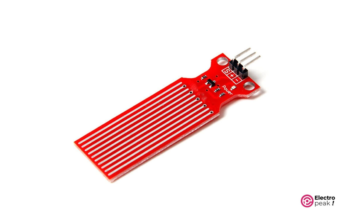
How does the water level sensor work?
Simply put: the output voltage of this sensor is proportional to the water depth.
This sensor contains ten parallel copper strips, five of which are power source lines, and the other five are signal lines. These ten strips are placed on the sensor one after the other. There is no connection between these two sets until a conductive liquid meets the surface of the strips. So, when there is no liquid, the resistance between these lines is extremely high, and, as a result, the strip voltage corresponding to the signal is zero. As the sensor is immersed in the water, we will have stronger conductivity between the two sets of strips, less resistance between the lines, and the S pin voltage gets closer to the positive pin voltage. In other words: the deeper the depth, the higher the voltage on the signal pin (of course, within the range of the power supply voltage).
Consider the following image as a basic model of how the rain sensor operates. As the sensor’s strips go under the water, the length of the resistance between the positive pin and the S pin decreases. As a result, the S pin voltage (Vs) gets closer to the power source voltage (Vcc), and vice versa.
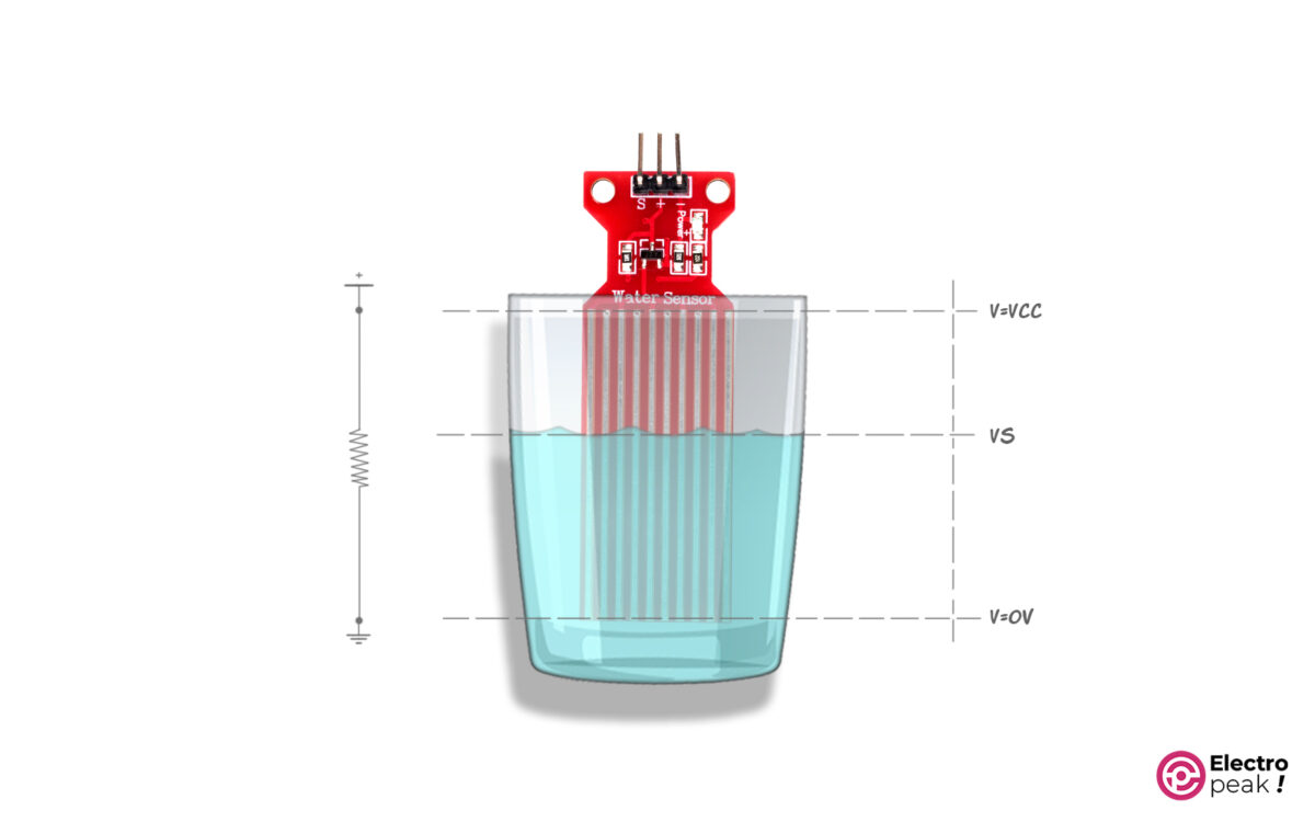
2- According to the principles mentioned above, both the liquid depth and conductivity have an impact on the output voltage. Water drops alone are enough to improve conductivity between the strips and increase the S-pin voltage.
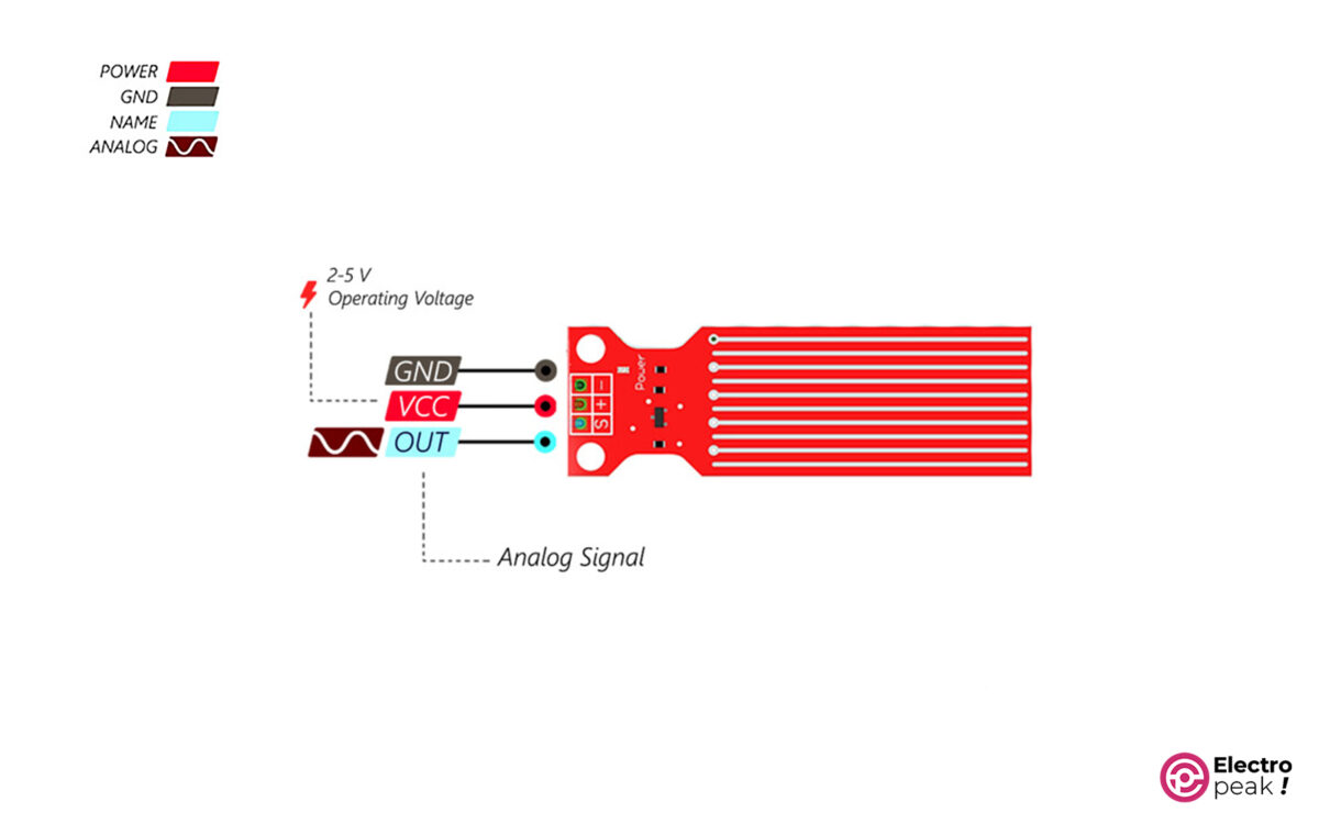
Water Level Detection Sensor Pinout
- -: Gnd
- +: power supply of the module (2 to 5 volts)
- S: the module output an as analog voltage
Hardware Components
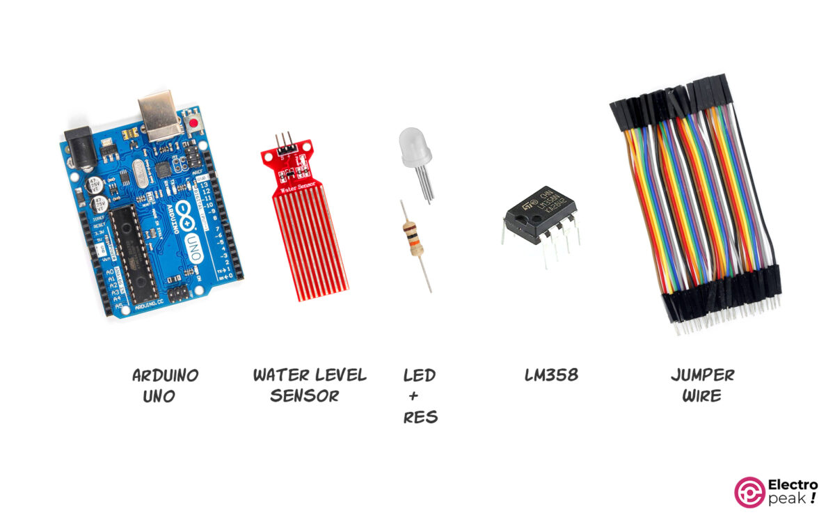
*: Despite having the same basic functionality, the water level detecting sensors come in three distinct brands and quality levels.
**: Only the first three items are needed to interface the water level sensor. The remaining components are used in the following projects.
Software
How to Test If The Water Level Sensor Works?
Without getting too complicated, let’s first test our sensor to see how it works:
Connect the sensor’s positive pin to the power supply positive pin and the sensor’s negative pin to the power supply Gnd (you can use the voltage output of your Arduino board as a power supply).
Set the multimeter to DC voltage measurement mode and measure the sensor’s S pin voltage in relation to Gnd (obviously, when the sensor is dry, it should be zero or a number close to zero). Now, lower the sensor slowly into the glass of water and, at various depths, read the voltage on the S pin (if your sensor is working properly, it should display a higher voltage in proportion to the water depth).
Interfacing Water Level Detection Sensor with Arduino
Wiring
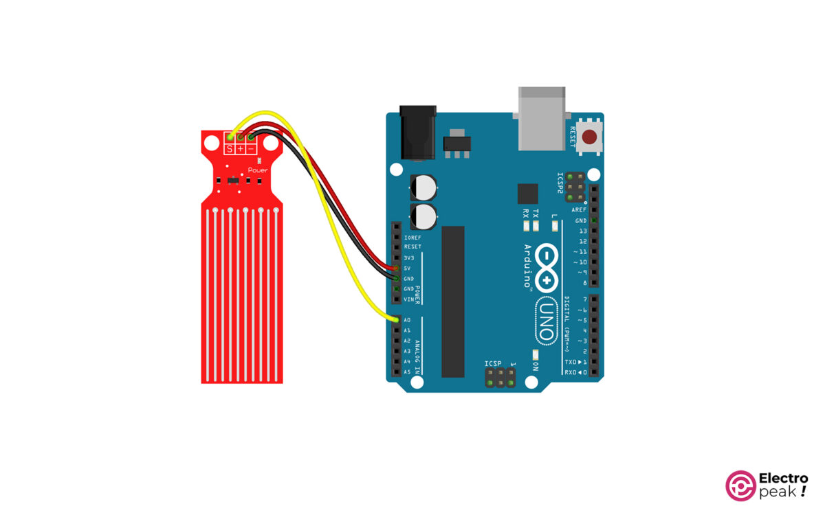
The S pin voltage is an analog voltage that must be read using the Arduino board’s analog inputs—one of the pins A0 to A5 on Arduino UNO. Here, we’ll go with the A0.
Code
No specific library is needed to interface the sensor with Arduino. Copy&paste the following code into the Arduino IDE software and upload it to the board.
/* Water level sensor
 * by Ali Akbar
 * https://electropeak.com/learn/
 */

#define sensorPin A0 // define pin A0 as sensorPin
int sensorValue = 0; // Value for storing water level

void setup() {
 Serial.begin(9600);
}

void loop() {
 sensorValue = analogRead(sensorPin); // reading pin A0 and store to sensorValue
 Serial.print("Sensor = " );
 Serial.println(sensorValue);
 delay(2000);
}
#define sensorPin A0: Since the A0 pin has been given a name in the code, instead of “A0,” we can simply call its name. This will make it easier to understand the complicated coding.
int sensorValue = 0;: We made a numeric variable with the type “Int” to store the information obtained from the sensor and then set its initial value to 0.
void setup() { Serial.begin(9600); }: Here, commands should be executed only once at the beginning. The Serial.begin(9600); Command enables serial communication with a transfer rate of 9600 for the communication between the Arduino board and the computer so that Arduino can use it to display the data in the serial port of the computer.
void loop() { }: Here, the commands must be called and updated regularly.
sensorValue = analogRead(sensorPin);: We read the analog value of pin A0 using the analogRead Command and then stored it in the sensorValuevariable. Serial.print("Sensor = " );
Serial.println(sensorValue);
delay(1000);: The loop() Commands are executed again, after a one-second delay.
Hold the sensor at different depths and see the changes on the Serial Monitor window.
Try to write down the numbers for a few specific depths, especially the deepest. Our measured number, in this case, is 691. Since the sensor consumes 20mA and we only need it to be on when reading data from the sensor, we can feed the sensor using one of the digital pins on the Arduino board. To do this, set the desired pin as an output and turn on/off the sensor pin by pulling it High/Low.
A function can be written to read the sensor information and call it when needed. This will make it easier to use the sensor in more complicated circuits and programs.
The principles above are used in the following example.
Example: Displaying Water Level using Colored LEDs
Say we have a water container (an aquarium, for example) and want to know when it is full. Three green, yellow, and red LEDs are used in this example to show three measurement levels.
Wiring
Connect the wires as shown below.

This time, we connected the sensor’s positive pin to a digital pin on Arduino—instead of connecting it directly to the power supply—so that we could simply turn the sensor on and off rather than leave it on all the time.
Code
Upload the code on your board.
/* Water level sensor
 * by Ali Akbar
 * https://electropeak.com/learn/
 */

#define sensorPin A0 // define pin A0 as sensorPin
#define vccPin 2 // define pin 2 as Vcc for sensor

int sensorValue = 0; // Value for storing water level
const int redLED = 3;
const int yellowLED = 4;
const int greenLED = 5;
const int sensorMin = 0; // sensor minimum
const int sensorMax = 700; // sensor maximum

void setup() {
 pinMode(vccPin, OUTPUT); // Set D2 as an OUTPUT
 digitalWrite(vccPin, LOW); // Set to LOW so no power flows through the sensor
 pinMode(redLED, OUTPUT);
 pinMode(yellowLED, OUTPUT);
 pinMode(greenLED, OUTPUT);
 // Initially turn off all LEDs
 digitalWrite(redLED, LOW);
 digitalWrite(yellowLED, LOW);
 digitalWrite(greenLED, LOW);
}

void loop() {
 Serial.begin(9600);
 sensorValue = readSensor(); //
 int range = map(sensorValue, sensorMin, sensorMax, 0, 3); // 3 levels
 switch (range) {
 case 0:
 digitalWrite(redLED, LOW);
 digitalWrite(yellowLED, LOW);
 digitalWrite(greenLED, HIGH);
 Serial.println("green");
 break;

 case 1: // Sensor getting wet
 digitalWrite(redLED, LOW);
 digitalWrite(yellowLED, HIGH);
 digitalWrite(greenLED, LOW);
 Serial.println("y");
 break;

 case 2: //
 digitalWrite(redLED, HIGH);
 digitalWrite(yellowLED, LOW);
 digitalWrite(greenLED, LOW);
 Serial.println("R");
 break;
 }
 delay(2000);
}

//This is a function used to get the reading
int readSensor() {
 digitalWrite(vccPin, HIGH); // Turn the sensor ON
 delay(10); // wait 10 milliseconds
 sensorValue = analogRead(sensorPin); // Read the analog value form sensor
 digitalWrite(vccPin, LOW); // Turn the sensor OFF
 return sensorValue; // send current reading
}
const int sensorMax = 690;: Stores the maximum value measured by the sensor in the sensorMax variable. This number can be different for everyone, but it has to be less than 1024. We obtained this number with the previous code. You can set 1024 or a smaller number by default, but the sensor may be less accurate in calculating the level depending on the type and manufacturer of the sensor.
In the setup() loop, specify the state of the pins, and the outputs must be initially set to zero.
sensorValue = readSensor();: Write a separate function to read the sensor information and call it every time with this command to save the returned value in the sensorValue variable.
int range = map(sensorValue, sensorMin, sensorMax, 0, 3);: Using the map Command, measure the value of the sensorValue variable between the minimum and maximum values of sensorMin and sensorMax in three equal ranges, and then save the specified ranges in the range variable. switch (range) {
case 0:
digitalWrite(redLED, LOW);
digitalWrite(yellowLED, LOW);
digitalWrite(greenLED, HIGH);
break;
case 1: // Sensor getting wet
digitalWrite(redLED, LOW);
digitalWrite(yellowLED, HIGH);
digitalWrite(greenLED, LOW);
break;
case 2: // Sensor dry
digitalWrite(redLED, HIGH);
digitalWrite(yellowLED, LOW);
digitalWrite(greenLED, LOW);
break;
}
delay(1000);
}switch/case, we measure the numerical value of the range and turn on the correct LED while turning off the others. int readSensor() {
digitalWrite(vccPin, HIGH); // Turn the sensor ON
delay(10); // wait 10 milliseconds
sensorValue = analogRead(sensorPin); // Read the analog value form sensor
digitalWrite(vccPin, LOW); // Turn the sensor OFF
return sensorValue; // send current reading
}
readSensor function to read the sensor information. In this function:
- The pin connected to the sensor’s positive pin goes High.
- The output value of the S pin is read and stored in the sensorValue variable.
- The value of sensorValue is returned as the positive pin goes Low.
How to Use Water Level Sensor without Arduino?
Although using microcontrollers, such as Arduino, to detect the humidity or water level is simple and efficient, it is not the easiest and cheapest option.
The output of the water level sensor is a variable voltage proportional to the water depth or humidity level. So, we can, early on, define a threshold value—an output voltage that indicates a certain level of water—and compare the sensor’s output voltage with this threshold value at any moment.
We can also use op-amps to compare two voltage levels. A reasonable and inexpensive option would be the Lm358 opamp.
The figure below is the schematic of the voltage comparator circuit, which can be used to build a water leak, overflow, or even shortage warning system.
Water Level & Rain Detection Circuit
In the figure below, R4 is a 10KΩ potentiometer. Also, the threshold voltage value is determined by the potentiometer’s output pin (blue lines). By adjusting the potentiometer, we can measure the threshold value based on the amount of water.
Now, when the sensor output voltage level (orange lines) is greater than the threshold level, the opamp at the bottom is activated, and LED 2 will be on. But when it falls below the threshold level, LED 1 will be on.
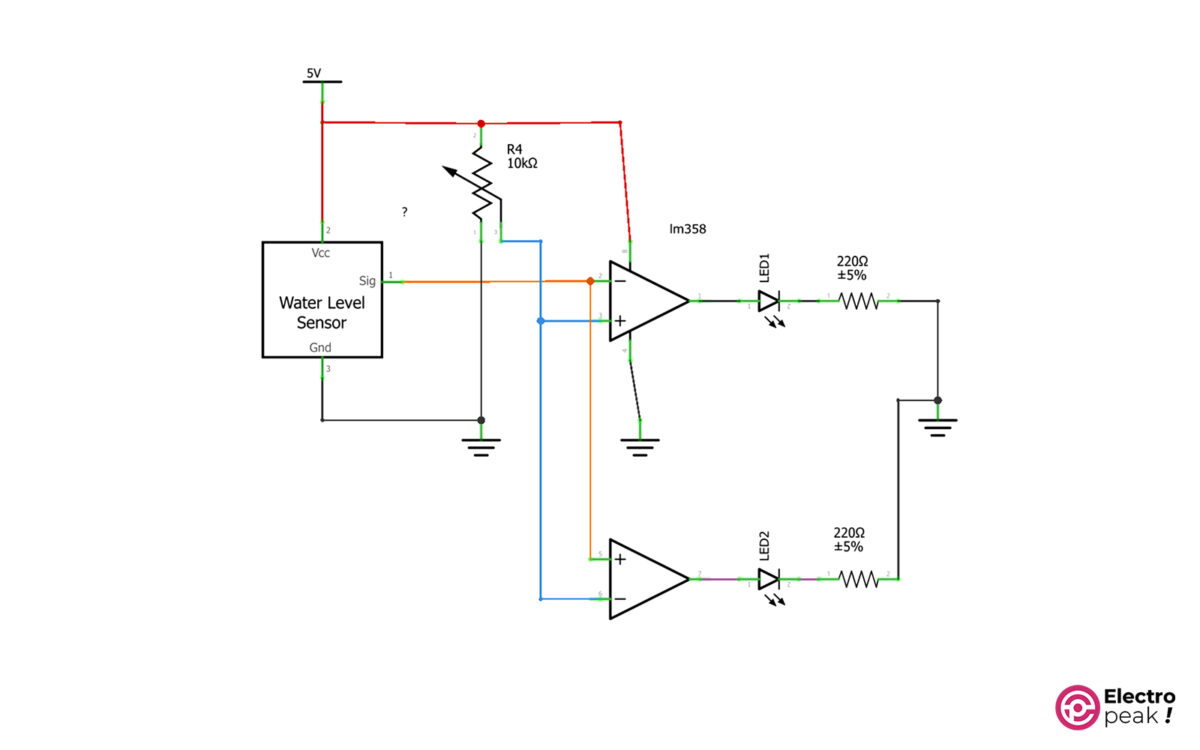
In the circuit above, instead of LEDs, we can use relay circuits to control actuators such as water pumps, alarm sirens, etc.
What’s next?
Water level monitoring: Use a Character LCD to display the relative amount of water in a container.
A smart aquarium: Build a water level warning or control system for an aquarium using a water level sensor with an operating range. If the water exceeds or falls below this range, it should alert us with a buzzer or switch on a water pump. (It’s pretty easy. You can build it with a comparator circuit. You don’t even need to use Arduino).

