
Overview
What You Will Learn
- General information about NodeMCU
- How to install ESP8266 based boards on Arduino IDE
- How to program NodeMCU on Arduino IDE
- Introducing boards that can be used instead of NodeMCU
What Is NodeMCU?
Today, IOT applications are on the rise, and connecting objects are getting more and more important. There are several ways to connect objects such as Wi-Fi protocol.
NodeMCU is an open source platform based on ESP8266 which can connect objects and let data transfer using the Wi-Fi protocol. In addition, by providing some of the most important features of microcontrollers such as GPIO, PWM, ADC, and etc, it can solve many of the project’s needs alone.
The general features of this board are as follows:
Easy to use
Programmability with Arduino IDE or IUA languages
Available as an access point or station
practicable in Event-driven API applications
Having an internal antenna
Containing 13 GPIO pins, 10 PWM channels, I2C, SPI, ADC, UART, and 1-Wire
How to program NodeMCU using Arduino IDE
In order to use Arduino IDE to program the NodeMCU, you have to introduce it to the software at first.
To do this copy the following code and follow the steps below:
http://arduino.esp8266.com/stable/package_esp8266com_index.json
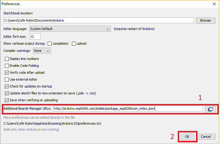
step1. Choose Preferences in the File menu and enter the copied code in Additional Board Manager URLs part. Then press OK.
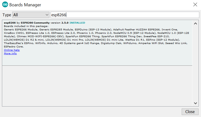
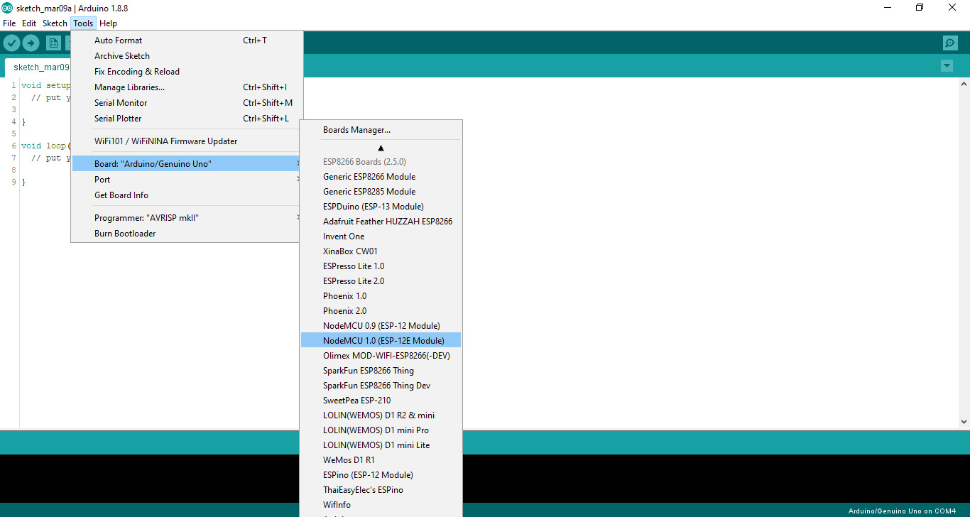
Step2. Search the word ESP8266 in Boards>boards manager from Tools menu. Then install ESP8266 boards. After complete installation, you will see the INSTALLED label on ESP8266 boards.
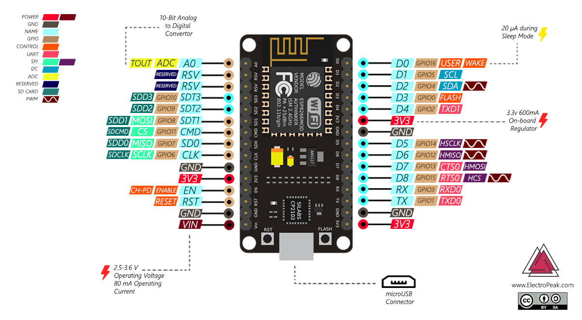
In order to use digital pins, you should select GPIO numbers. For example, the D7 pin is defined as GPIO13. So you should set up the pin number 13 whenever you want to use D7 in your program. Also, you can use pin D2(GPIO4) as SDA and pin D1(GPIO5) as SCL
Controlling LED through an HTTP page Using NodeMCU
Code
#include <ESP8266WiFi.h>
#include <WiFiClient.h>
#include <ESP8266WebServer.h>

/* Set these to your desired credentials. */
const char *ssid = "*****"; //Enter your WIFI ssid
const char *password = "*****"; //Enter your WIFI password

ESP8266WebServer server(80);

void handleRoot() {
  server.send(200, "text/html", "<form action=\"/LED_BUILTIN_on\" method=\"get\" id=\"form1\"></form><button type=\"submit\" form=\"form1\" value=\"On\">On</button><form action=\"/LED_BUILTIN_off\" method=\"get\" id=\"form2\"></form><button type=\"submit\" form=\"form2\" value=\"Off\">Off</button>");
}
void handleSave() {
  if (server.arg("pass") != "") {
    Serial.println(server.arg("pass"));
  }
}
void setup() {
  pinMode(LED_BUILTIN, OUTPUT);
  delay(3000);
  Serial.begin(115200);
  Serial.println();
  Serial.print("Configuring access point...");
  WiFi.begin(ssid, password);
  while (WiFi.status() != WL_CONNECTED) {
    delay(500);
    Serial.print(".");
  }
  Serial.println("");
  Serial.println("WiFi connected");
  Serial.println("IP address: ");
  Serial.println(WiFi.localIP());
  server.on ( "/", handleRoot );
  server.on ("/save", handleSave);
  server.begin();
  Serial.println ( "HTTP server started" );
  server.on("/LED_BUILTIN_on", []() {
    digitalWrite(LED_BUILTIN, 1);
    Serial.println("on");
    handleRoot();
  });
  server.on("/LED_BUILTIN_off", []() {
    digitalWrite(LED_BUILTIN, 0);
    Serial.println("off");
    handleRoot();
  });
}
void loop() {
  server.handleClient();
}What other boards can I use instead of NodeMCU?
| Board | Cost $ | Voltage | GPIO | ADC | PWM | UART | SPI | I2C | Internal antenna | Special Features |
|---|---|---|---|---|---|---|---|---|---|---|
| Nodemcu | 8.39 | 5 | 13 | 1 | 10 | 2 | Yes | Yes | Yes | User LED – RESET and FLASH Buttons |
| Esp8266-01 module | 4.55 | 3.3 | 2 | 1 | 0 | 1 | No | No | Yes | - |
| Wemos D1 mini | 2.04 | 5 | 11 | 1 | 10 | 3 | Yes | Yes | Yes | RESET and FLASH Buttons |
| Witty Cloud | 16.50 | 5 | 9 | 1 – connected to LDR | 9 | 1 | Yes | Yes | Yes | LDR – RGB – 3x Buttons – User LED |
| Esp8266-12 Module | 4.99 | 3.3 | 13 | 1 | 12 | 3 | Yes | Yes | Yes | - |
| ESP8266-12E module | 4.50 | 3.3 | 17 | 1 | 4 | 2 | Yes | Yes | Yes | - |
| ESP-201 | 6.59 | 3.3 | 15 | 1 | 15 | 2 | Yes | Yes | Yes | - |
| Adafruit HUZZAH | 11.99 | 5 | 9 | 1 | 9 | 2 | Yes | Yes | Yes | RESET and User Buttons – User LED |
| BRKWSO1 | 23.88 | 3.3 | 9 | - | - | 1 | - | - | No | - |
