
Introduction
In this tutorial, we will explore the potential of infrared (IR) technology and how it can be utilized with an Arduino. Infrared communication is a common feature in electronic devices that allows wireless information exchange. IR technology is everywhere, from remote controls to automatic doors. Understanding the principles of IR communication and learning how to work with it will open up a wide range of possibilities. This tutorial will help you send and receive IR signals with an Arduino. We’ll cover the basics of IR communications, including different protocols and codes, as well as practical examples to help you get started.
What You Will Learn
- How IR communication works
- Applications of IR technology
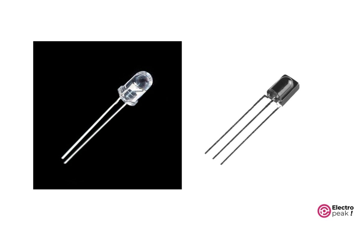
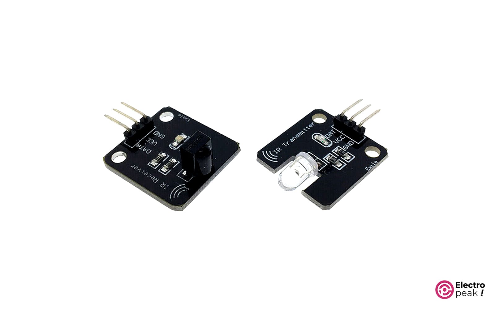
- Getting to know the IR transmitter and receiver
- Communicating with two Arduinos using IR
What is IR Communication?
IR communication is a common, inexpensive, and simple wireless communication technology. Infrared light is very similar to visible light, except that it has a slightly longer wavelength. This means that IR radiation is invisible to the human eye, making it suitable for data exchange.
IR communication is limited to short distances and it requires a direct line of sight. It also cannot pass through walls.
Due to these limitations of IR, it is difficult to track communications. In fact, communication between infrared devices is usually one-to-one. Therefore, the data transmitted in this method is usually not encrypted.
When you use IR wireless control, an LED in the infrared spectrum is used to transmit data to the receiver. But there are various IR sources around us. The sun, light bulbs, or anything else that produces heat are very bright in the infrared spectrum.
Therefore, the IR receiver must be able to distinguish the remote’s signals from the ambient IR signals. For this purpose, we use the modulated IR signal. Modulating a signal is like assigning a pattern to the data to ensure the receiver can recognize it.
A common modulation for IR communications is 38 kHz modulation. There are few natural sources of 38kHz signal waves, so an IR transmitter using that frequency will differ from ambient IR waves.
When you press a key on your remote, the IR transmitter’s LED will flash quickly in a fraction of a second, transmitting coded data to the receiver.
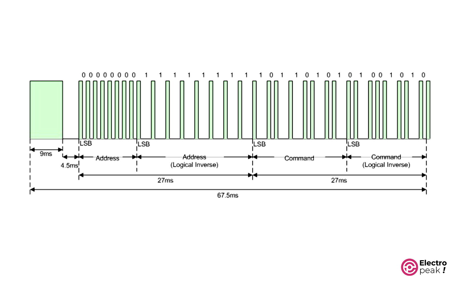
The data transmitted through IR—in addition to their main frequency of 38 kHz—have their own protocols. For example, the NEC protocol—which was and is widely used by Japanese appliance manufacturers—transmits data in the following format.
So far, we’ve learned about IR transmitters and receivers and how to communicate between them. Now, let’s see how we can use this method to communicate between two Arduino boards and transmit and receive commands between them.
Reqiured Materials
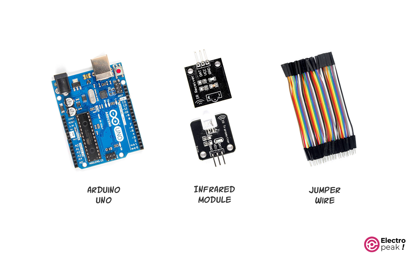
IR Communication between two Arduino Boards
As mentioned before, we will build two separate circuits with Arduino. The first circuit uses a 38 kHz infrared sensor to receive the IR signal and an Arduino controller to interpret the input signal. The second circuit includes an infrared transmitter LED module to send IR codes to the receiver and an Arduino controller.
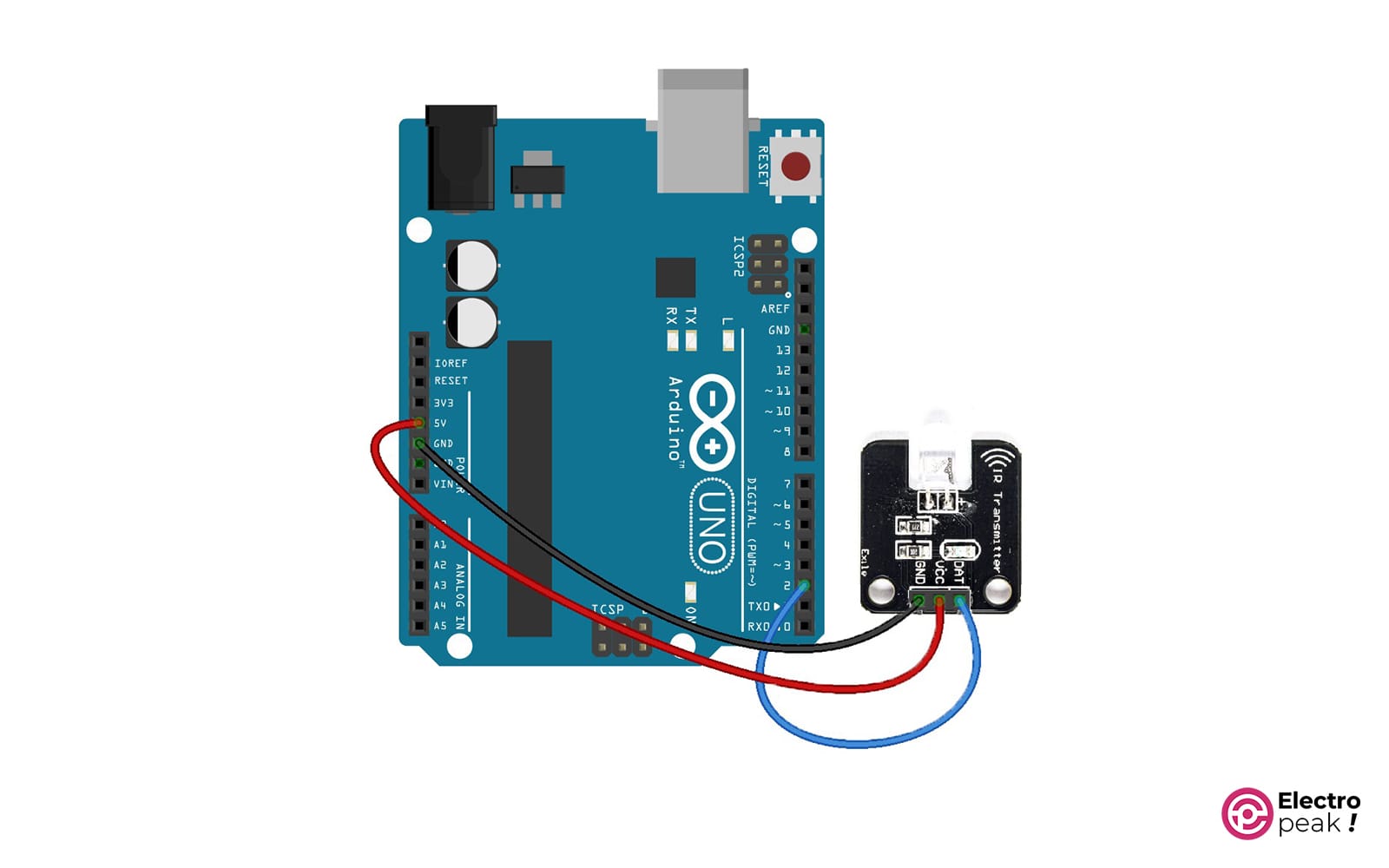
Wiring
Here is the circuit for the transmitter:
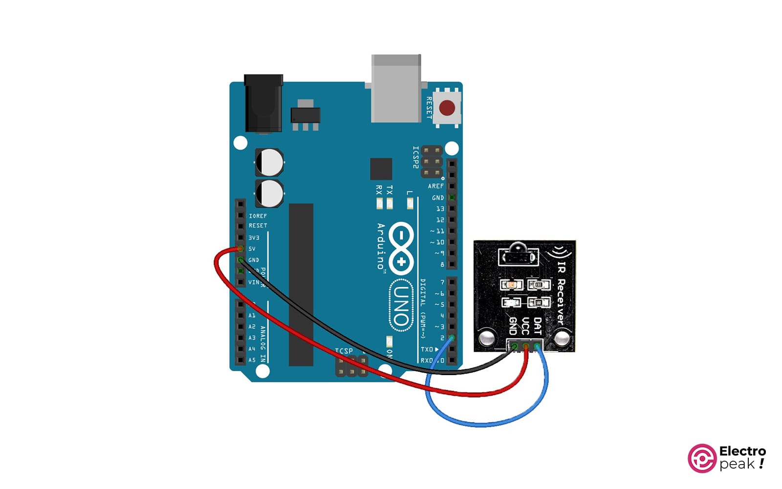
And here is the circuit for the receiver:
Arduino Code for IR Transmitter
First, download the IRremote library from this link and install it. Next, download the Sender file from here and then open it in the Arduino IDE software.
/*
  modified on AUG 23, 2023
  Modified by MajidMerati from Arduino Examples
  Home
*/

#include <Arduino.h>

#define DISABLE_CODE_FOR_RECEIVER // Disables restarting receiver after each send. Saves 450 bytes program memory and 269 bytes RAM if receiving functions are not used.
//#define SEND_PWM_BY_TIMER         // Disable carrier PWM generation in software and use (restricted) hardware PWM.
//#define USE_NO_SEND_PWM           // Use no carrier PWM, just simulate an active low receiver signal. Overrides SEND_PWM_BY_TIMER definition

/*
   This include defines the actual pin number for pins like IR_RECEIVE_PIN, IR_SEND_PIN for many different boards and architectures
*/
#include "PinDefinitionsAndMore.h"
#include <IRremote.hpp> // include the library

void setup() {
  pinMode(LED_BUILTIN, OUTPUT);
  Serial.begin(115200);
  pinMode(10, INPUT_PULLUP);
  pinMode(11, INPUT_PULLUP);
  pinMode(12, INPUT_PULLUP);

  Serial.print(F("Send IR signals at pin ")); //Printouts the IR send pin used in the chip you want.
  Serial.println(IR_SEND_PIN);

  //    IrSender.begin(); // Start with IR_SEND_PIN as send pin and if NO_LED_FEEDBACK_CODE is NOT defined, enable feedback LED at default feedback LED pin
  IrSender.begin(DISABLE_LED_FEEDBACK); // Start with IR_SEND_PIN as send pin and disable feedback LED at default feedback LED pin
}

/*
   Set up the data to be sent.
   For most protocols, the data is build up with a constant 8 (or 16 byte) address
   and a variable 8 bit command.
   There are exceptions like Sony and Denon, which have 5 bit address.
*/
uint8_t saddress = 0;
uint8_t sCommand = 0;
uint8_t sRepeats = 0;

void loop() {
  if (digitalRead(10) == LOW)
  {
    saddress = 0x00;
    sCommand = 0x10;
    sRepeats = 1;
  }
  else if (digitalRead(11) == LOW)
  {
    saddress = 0x01;
    sCommand = 0x20;
    sRepeats = 1;
  }
  else if (digitalRead(12) == LOW)
  {
    saddress = 0x02;
    sCommand = 0x30;
    sRepeats = 1;
  }
  if (digitalRead(10) == LOW || digitalRead(11) == LOW || digitalRead(12) == LOW)
  {
    /*
      Print current send values
    */
    Serial.println();
    Serial.print(F("Send now: address=0x"));  Serial.print(saddress, HEX);
    Serial.print(F("command=0x"));            Serial.print(sCommand, HEX);
    Serial.print(F(", repeats="));            Serial.print(sRepeats);
    Serial.println();

    Serial.println(F("Send standard LG with 8 bit address"));
    Serial.flush();
    IrSender.sendLG(saddress, sCommand, sRepeats);
  }


  delay(1000);  // delay must be greater than 5 ms (RECORD_GAP_MICROS), otherwise the receiver sees it as one long signal
}
To understand the code better, you can read the comments written next to them.
This code reads the status of Arduino pins 10, 11, and 12 and if any of them is connected to GND, it transmits a message containing different commands with a different address. The protocol used is LG. By changing the sRepeats variable, you can set the number of message repetitions per transmission.
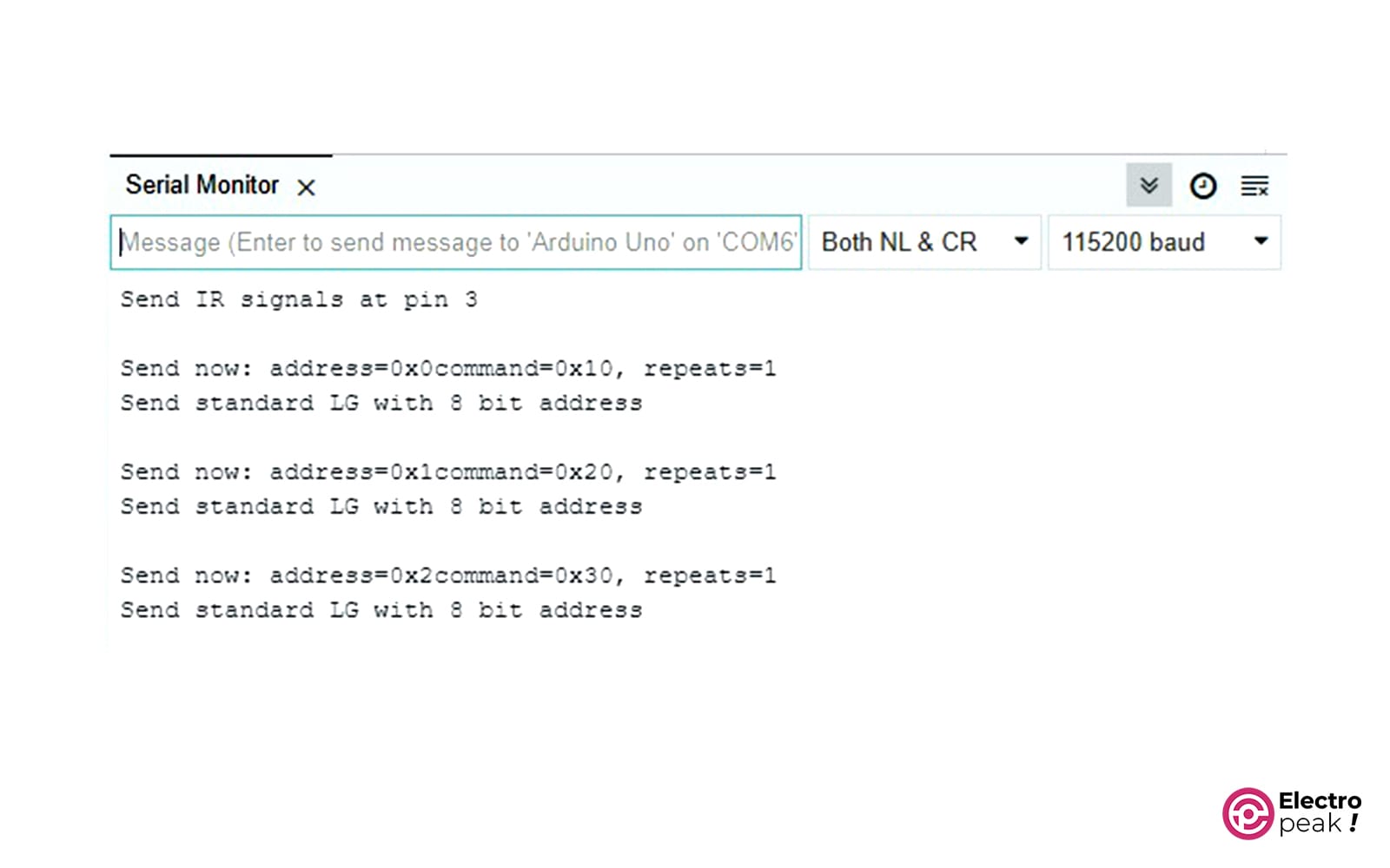
The transmitted data can also be viewed in the Serial Monitor. To do this, you need to open it in the Arduino IDE software and then set the baud rate to 115200.
Arduino Code for IR Receiver
Download the Receiver file from this link and open it in the Arduino IDE software.
/*
  modified on AUG 23, 2023
  Modified by MajidMerati from Arduino Examples
  Home
*/

/*
 * Specify which protocol(s) should be used for decoding.
 * If no protocol is defined, all protocols (except Bang&Olufsen) are active.
 * This must be done before the #include <IRremote.hpp>
 */
//#define DECODE_DENON        // Includes Sharp
//#define DECODE_JVC
//#define DECODE_KASEIKYO
//#define DECODE_PANASONIC    // alias for DECODE_KASEIKYO
#define DECODE_LG
#define DECODE_NEC          // Includes Apple and Onkyo
//#define DECODE_SAMSUNG
//#define DECODE_SONY
//#define DECODE_RC5
//#define DECODE_RC6

//#define DECODE_BOSEWAVE
//#define DECODE_LEGO_PF
//#define DECODE_MAGIQUEST
//#define DECODE_WHYNTER
//#define DECODE_FAST

//#define DECODE_DISTANCE_WIDTH // Universal decoder for pulse distance width protocols
//#define DECODE_HASH         // special decoder for all protocols

//#define DECODE_BEO          // This protocol must always be enabled manually, i.e. it is NOT enabled if no protocol is defined. It prevents decoding of SONY!

//#define DEBUG               // Activate this for lots of lovely debug output from the decoders.

//#define RAW_BUFFER_LENGTH  180  // Default is 112 if DECODE_MAGIQUEST is enabled, otherwise 100.

#include <Arduino.h>

/*
 * This include defines the actual pin number for pins like IR_RECEIVE_PIN, IR_SEND_PIN for many different boards and architectures
 */
#include "PinDefinitionsAndMore.h"
#include <IRremote.hpp> // include the library

void setup() {
    Serial.begin(115200);

    // Start the receiver and if not 3. parameter specified, take LED_BUILTIN pin from the internal boards definition as default feedback LED
    IrReceiver.begin(IR_RECEIVE_PIN, ENABLE_LED_FEEDBACK);

    Serial.print(F("Ready to receive IR signals of protocols: "));
    printActiveIRProtocols(&Serial);
    Serial.println(F("at pin " STR(IR_RECEIVE_PIN))); //Printouts the IR receive pin used in the chip you want.
}

void loop() {
    /*
     * Check if received data is available and if yes, try to decode it.
     * Decoded result is in the IrReceiver.decodedIRData structure.
     */
    if (IrReceiver.decode()) {

        /*
         * Print a short summary of received data
         */
        IrReceiver.printIRResultShort(&Serial);
        IrReceiver.printIRSendUsage(&Serial);
        if (IrReceiver.decodedIRData.protocol == UNKNOWN) {
            Serial.println(F("Received noise or an unknown (or not yet enabled) protocol"));
            // We have an unknown protocol here, print more info
            IrReceiver.printIRResultRawFormatted(&Serial, true);
        }
        Serial.println();

        /*
         * !!!Important!!! Enable receiving of the next value,
         * since receiving has stopped after the end of the current received data packet.
         */
        IrReceiver.resume(); // Enable receiving of the next value

        /*
         * Finally, check the received data and perform actions according to the received command
         */
        if (IrReceiver.decodedIRData.command == 0x10) {
            // do something
            Serial.println("received command 10");
        } else if (IrReceiver.decodedIRData.command == 0x20) {
            // do something else
            Serial.println("received command 20");
        } else if (IrReceiver.decodedIRData.command == 0x30) {
            // do something else
            Serial.println("received command 30");
        }
    }
}
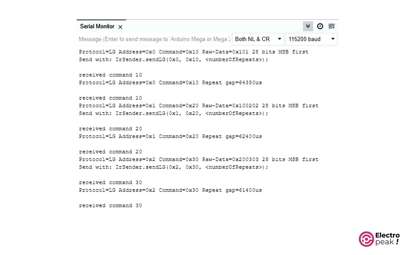
In this code, the Arduino board waits to receive an IR signal and prints a message on the Serial Monitor if the received data format is correct, based on its command and address.
Example Test For Arduino IR Communication
After programming both Arduino boards, make sure that the LED on the transmitter and the diode on the IR receiver are facing each other. Now, if you connect one of the pins of 10, 11, or 12 on the transmitter board to GND, the corresponding address and command will be transmitted to the receiver.
You can view the transmitted and received data respectively on the Serial Monitor of the transmitter and receiver. Here, we tested all three modes by connecting pins 10, 11, or 12 to the GND. As you can see, the commands corresponding to each pin have been transmitted and received.
What’s Next?
In this tutorial, we learned about the basic concepts of IR transmitters and receivers and their various types. Using what you have learned, you can now build all kinds of remote communication systems.
To develop the program you wrote, you can design an IR transmitter or receiver with ESP8266 or ESP32. The library written for these two controllers supports different protocols. So you can build a universal transmitter or receiver that can communicate with all remote controllers.
You can download this library from here.
For example, with a universal transmitter device, you can simultaneously communicate with several devices and control them with IR receivers. For this, you just need to build a universal receiver and read and copy the protocol and data codes transmitted by different remote controllers. If you include them when transmitting IR signals on your universal transmitter, you can control the receivers.
