Interfacing X9C104 100K Digital Potentiometer Module with Arduino
Written by
Mehran Maleki
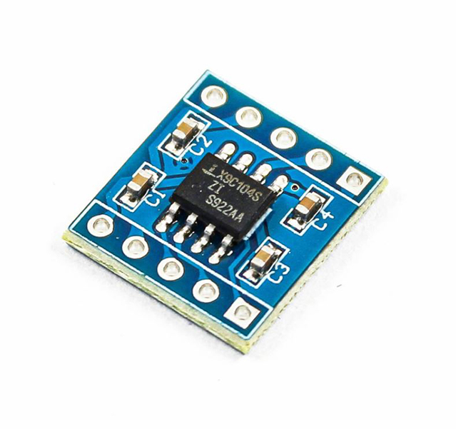
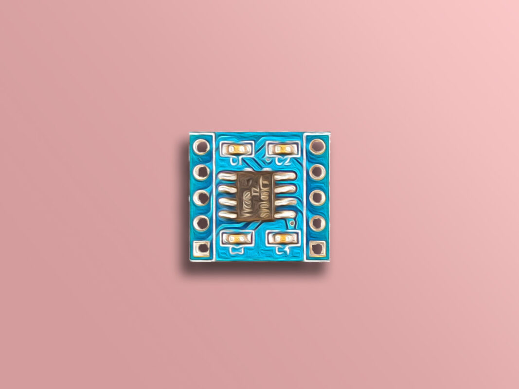
X9C104 100K Digital Potentiometer Module Features
The X9C104 digital potentiometer module is a variable resistor whose resistance value can be set digitally by a microcontroller. It consists of 3 output pins (RH، RW و RL) which can replace a mechanical potentiometer which has 3 pins. This module has 99 resistance components and its resistor is controlled by a 3-wire interface.
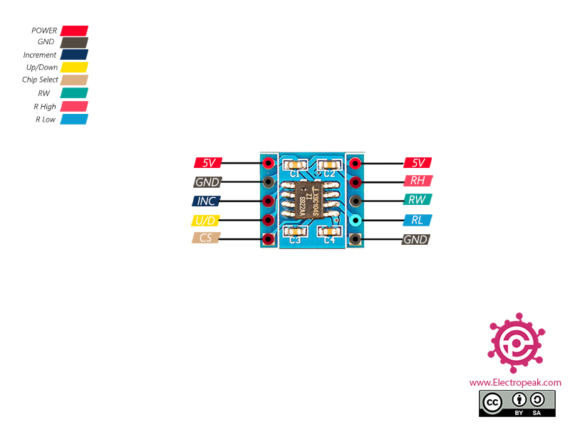
X9C104 100K Digital Potentiometer Module Pinout
This sensor has 10 pins:
5 pins on the left side:
VCC: Module power supply – 5V
GND: Ground
INC: Changing resistor command
U/D: UP / Down. Adjusting resistor
CS: Chip Select. Active LOW
5 pins on the right side:
VCC: Module power supply – 5V
RH: Resistor High
RW: Regulated Resistor
RL: Resistor Low
GND: Ground
Note
The 3 RH, RW and RL pins can replace a mechanical potentiometer which has 3 pins
You can see the pinout of this module here.
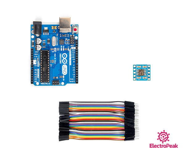
Required Material
Hardware component
Arduino UNO R3R3
×
1
X9C104 100K Digital Potentiometer Module
×
1
Male to Female Jumper wire
×
1
Software Apps
Arduino IDE
Interfacing X9C104 100K Digital Potentiometer Module with Arduino
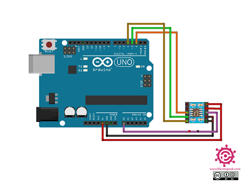
Step 1: Circuit
The following circuit shows how you should connect Arduino to X9C104 module. Connect wires accordingly.
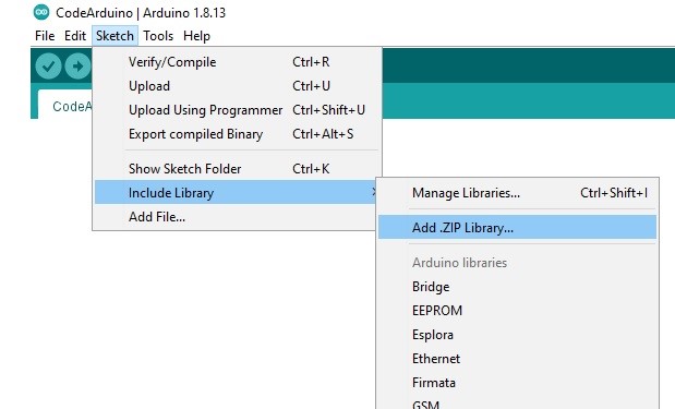
Step 2: Installing Library
Download the DigiPotX9Cxxx library here. Then go to the Include Library and install the library.
In this code, the Arduino pins 2, 3 and 4 are connected to the INC, U/D and CS, respectively. Then, at first the variable output voltage goes up and then goes down. The output value is read by Arduino pin A0 and displayed in the Serial Plotter.
Hi,
There can actually be different symbols representing the positive end of the power supply. And among them VCC and +ve are the most popular ones. So, they can be used alternatively.
Please help me if you can. I need to use the x9c to regulate either power on, or power completely off. I understood the RH HIGH is complete resistance (no power) and RH LOW is very little resistance (nearly full power). Did I get that right?
Hello, I have a question regarding stepping of the resistance. If I pulse up from 0 up to more than 100 steps, will the resistance “roll over” zero, or will it ramp and stay on the maximum?
Thank you in advance for info.
there are 3 potentiometer in this module
1) 1st to control load in voltage which is around 8volt to 60 volt
2) 2nd to control Current which is around 20amp
3) 3rd to control load out voltage which is around 12volt to 100 volt.
i did not able to figure out that this module can regulate 100 volt or not, because in the product description 5volt mention. but same mechanical potentiometer 100k ohm can regulate 100 volt which is already used in boost converter module.
Hi ajinkya,
According to the datasheet, the maximum input voltage of this module is positive and negative 5 volts. Therefore, you cannot use it for your case.
You can read the value between RL and RW, but it might not work as you intend.
In this case, you should set a voltage between RH, RL and use a voltmeter between RL and RW to observe the changing value.


Comments (14)
Thanks for this very good tutorial.
Worked perfectly.
You’re quite welcome. We always try to do our best.
Thanks for the nice info.
Your pinout says “VCC: Module power supply – 5V”.
This should be Vcc is +ve ?
Hi,
There can actually be different symbols representing the positive end of the power supply. And among them VCC and +ve are the most popular ones. So, they can be used alternatively.
Please help me if you can. I need to use the x9c to regulate either power on, or power completely off. I understood the RH HIGH is complete resistance (no power) and RH LOW is very little resistance (nearly full power). Did I get that right?
Hi. You’re absolutely correct.
Hello, I have a question regarding stepping of the resistance. If I pulse up from 0 up to more than 100 steps, will the resistance “roll over” zero, or will it ramp and stay on the maximum?
Thank you in advance for info.
Hi
it goes to zero when touch the maximum level
Hi,
thanks for this detail explaination of useing thise moduel, we really get more information from your effort.
can you please tell me, can i replace this with mechanical potentiometer of dc to dc boost converter 1200 watt (check product link).
https://www.electronicscomp.com/1200w-dc-dc-boost-step-up-converter-8-60v-to-12-83v-20a?gclid=Cj0KCQjwyLGjBhDKARIsAFRNgW-BdkgFSU458Sl1GWV5YWH3Vno21pJQ5Yo3iycCH9Sk6af2-uOw2hkaAqEQEALw_wcB
there are 3 potentiometer in this module
1) 1st to control load in voltage which is around 8volt to 60 volt
2) 2nd to control Current which is around 20amp
3) 3rd to control load out voltage which is around 12volt to 100 volt.
i did not able to figure out that this module can regulate 100 volt or not, because in the product description 5volt mention. but same mechanical potentiometer 100k ohm can regulate 100 volt which is already used in boost converter module.
Hi ajinkya,
According to the datasheet, the maximum input voltage of this module is positive and negative 5 volts. Therefore, you cannot use it for your case.
thanks for your replay,
but does it possible if i add resistor 22k for 100 volt load to this module
Which pins can I connect an OHM meter so that I can observe the INCREASE/DECREASE in resistance as INC is pulsed?
Hello Seymour,
You can read the value between RL and RW, but it might not work as you intend.
In this case, you should set a voltage between RH, RL and use a voltmeter between RL and RW to observe the changing value.
Many thanks!