Interfacing X9C103S Digital Potentiometer Module with Arduino
Written by
Mehran Maleki
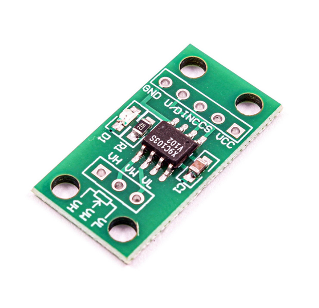
X9C103S Digital Potentiometer Module Features
The X9C103S 10k digital potentiometer module is a variable resistor whose resistance value can be varied digitally from a microcontroller. It consists of a 3-pin output which can replace a mechanical potentiometer which has 3 pins. This module has 99 resistance components and the final resistor is controlled by a 3-wire interface.
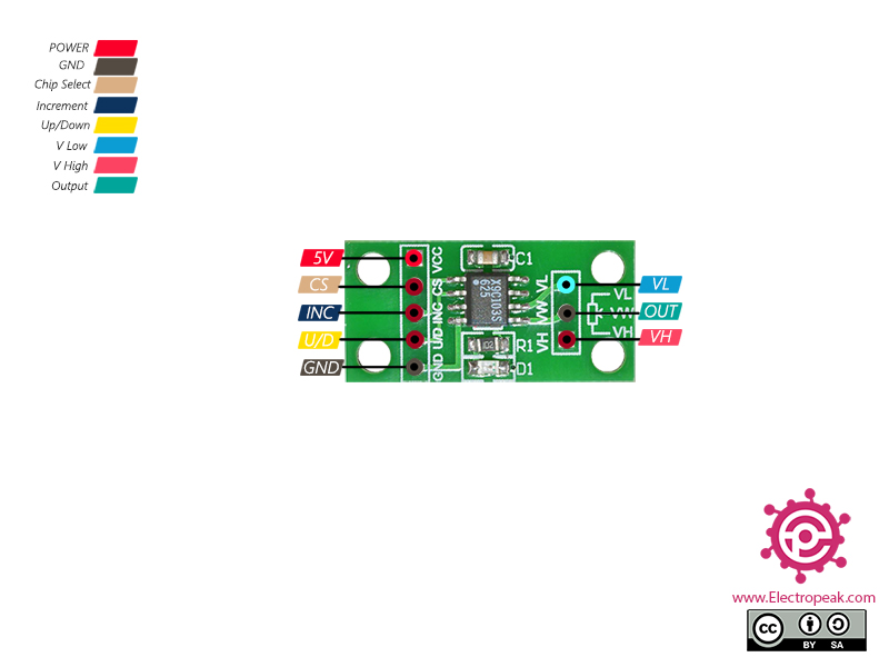
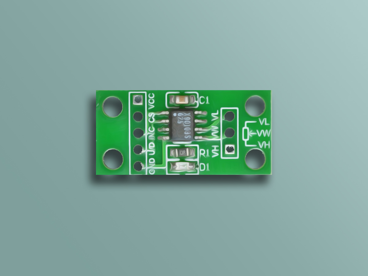
X9C103S Digital Potentiometer Module Pinout
This sensor has 8 wires:
VCC: Module power supply – 5V
CS: Chip Select. Active LOW
INC: Changing resistor command
U/D: UP / Down. Adjusting resistor
GND: Ground
VL: Voltage Low
VW: Voltage Wiper is the voltage output of the adjustable wiper contact
VH: Voltage High
Note
The 3-pin output can replace a mechanical potentiometer which has 3 pins.
You can see the pinout of this module here.
Required Materials
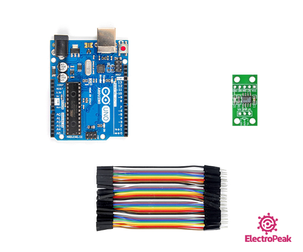
Hardware Components
Arduino UNO R3
×
1
10K X9C103S Digital Potentiometer Module
×
1
male-female-jumper-wire
×
1
Software Apps
Arduino IDE
Interfacing X9C103S Digital Potentiometer Module with Arduino
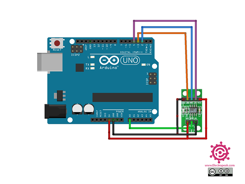
Step 1: Circuit
The following circuit shows how you should connect Arduino to X9C103S module. Connect wires accordingly.
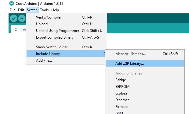
Step 2: Installing Library
Download theDigiPotX9Cxxxlibraryhere. Then go to the Include Library and install the library.
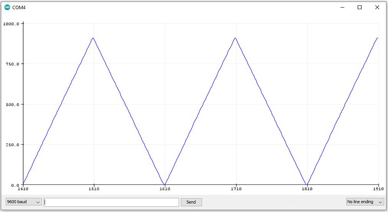
In this code, the Arduino pins 2, 3 and 4 are first connected to the INC, U / D and CS, respectively. Then, first the variable output voltage goes up and then down. The output value which is set by the Arduino is read by pin A0 and displayed in the Serial Plotter.
I would like to attach a button (a momentary button or switch) to make the potentiometer increase slowly when the momentary button is clicked, and then decrease slowly when the momentary button is clicked. How can I do that. I know enough electronics to be dangerous. Also, can I connect this shield to an Ardino Nano or smaller?
Hi.
The code provided here is to increase and decrease the resistance of the potentiometer over time, and what you want to do is to have a button to control this increasing and decreasing of the potentiometer. It’s possible and that’s how you can do that: Use one of the digital pins of your microcontroller as the input of the button. Put the increasing and decreasing parts of the code in an if statement and use the state of the button as the condition of that if statement. Then the potentiometer will only change if the button is pressed.
And about your last question, yes. You can connect this module to an Arduino Nano or any other Arduino board and use the same code.
Hello my friend. Thanks for your attention! It seems that something has gone wrong while uploading the article on the website.
Now the post is updated, and the pinout picture is replaced with the correct one.
Hi
You can use the following code to do just that.
Also, you can head over to this link in order to wire the buttons.
/*

  Modified on Nov 16, 2020

  Modified by MehranMaleki from Arduino Examples

  Home

*/
/*
For this example, connect your X9C103P (or the like) as follows:
1 - INC - Arduino pin 2
2 - U/D - Arduino pin 3
3 - VH - 5V
4 - VSS - GND
5 - VW - Output: Arduino pin A0 for analogRead
6 - VL - GND
7 - CS - Arduino pin 4
8 - VCC - 5V
*/
#define B1 7
#define B2 8
Thank you for this amazing step by step guidance on using programmable potentiometer.
I successfully designed the circuit and obtained the data in Arduino.
For verifying the obtained data of resistance values in Arduino, I tried to do the measurement simultaneously by multimeter but unfortunately, I did not observe anything in the multimeter.
And secondly I want to use this variable resistor values across my solar to observe varying voltage and current, How can I use it for that.
Hello.
Glad to hear that. You are welcome.
Firstly, you can’t measure the resistor value of this IC with a multimeter.
Secondly, to measure the voltage in Arduino, you should use a voltage divider. And to measure the current, you should use a current sensor such as INA219


Comments (13)
I would like to attach a button (a momentary button or switch) to make the potentiometer increase slowly when the momentary button is clicked, and then decrease slowly when the momentary button is clicked. How can I do that. I know enough electronics to be dangerous. Also, can I connect this shield to an Ardino Nano or smaller?
Hi.
The code provided here is to increase and decrease the resistance of the potentiometer over time, and what you want to do is to have a button to control this increasing and decreasing of the potentiometer. It’s possible and that’s how you can do that: Use one of the digital pins of your microcontroller as the input of the button. Put the increasing and decreasing parts of the code in an if statement and use the state of the button as the condition of that if statement. Then the potentiometer will only change if the button is pressed.
And about your last question, yes. You can connect this module to an Arduino Nano or any other Arduino board and use the same code.
I thing that the module’s pinout picture is wrong.
Hello my friend. Thanks for your attention! It seems that something has gone wrong while uploading the article on the website.
Now the post is updated, and the pinout picture is replaced with the correct one.
Hi please can you send me a complete code using a button to increase and decrease values ?
Hi
You can use the following code to do just that.
Also, you can head over to this link in order to wire the buttons.
/*
Modified on Nov 16, 2020
Modified by MehranMaleki from Arduino Examples
Home
*/
/*
For this example, connect your X9C103P (or the like) as follows:
1 - INC - Arduino pin 2
2 - U/D - Arduino pin 3
3 - VH - 5V
4 - VSS - GND
5 - VW - Output: Arduino pin A0 for analogRead
6 - VL - GND
7 - CS - Arduino pin 4
8 - VCC - 5V
*/
#define B1 7
#define B2 8
#include <DigiPotX9Cxxx.h>
DigiPot pot(2, 3, 4);
void setup() {
Serial.begin(9600);
pinMode(B1, INPUT_PULLUP);//put PULL_UP resistor
pinMode(B2, INPUT_PULLUP);//put PULL_UP resistor
}
void loop() {
Serial.println("Starting");
if (digitalRead(B1) == LOW) {
pot.increase(1);
Serial.println(analogRead(A0));
delay(20);
}
if (digitalRead(B2) == LOW) {
pot.decrease(1);
Serial.println(analogRead(A0));
delay(20);
}
}
Hi Thank you
I am going to do that !!
Hi
I have been triet to do an arduino circuit without success .. Please can you send me a complete arduino circuit using potentiometer and button …
So I had tested arduino code could see that not increase or decrease step to step 1 value ..
Please check what is necessary to correct to do increase and decrease processed analogic port data to control 0 until 5 volts
/*
For this example, connect your X9C103P (or the like) as follows:
1 – INC – Arduino pin 2
2 – U/D – Arduino pin 3
3 – VH – 5V
4 – VSS – GND
5 – VW – Output: Arduino pin A0 for analogRead
6 – VL – GND
7 – CS – Arduino pin 4
8 – VCC – 5V
*/
#include
#define B1 7
#define B2 8
#include
float floorVoltage = 0.5;
float ceilingVoltage = 4.5;
uint16_t pressure;
DigiPot pot(2,3,4); // 2-INC(Increment),3-UD(up and down),4-CS (chip select)
void setup() {
Serial.begin(9600);
pinMode(B1, INPUT_PULLUP);// define Botao1 como entrada
pinMode(B2, INPUT_PULLUP);// define Botao2 como entrada
}
void loop() {
if (digitalRead(B1) == LOW) { // se o botao B1 for pressionado
for (int i=0; i<10; i++)
//.increase(1);
for(int cnt=0; cnt<100; cnt++)
Serial.println(analogRead(A0));
pressure=(mapf(analogRead(A0),0,1023,0,5));
Serial.println(mapf(pressure, floorVoltage, ceilingVoltage, 0, 5));
delay(20);
}
if (digitalRead(B2) == LOW) { // se o botao B2 for pressionado
for (int i=0; i= 0; cnt–)
Serial.println(analogRead(A0));
float pressure=(mapf(analogRead(A0),0,1023,0,5));
Serial.println(mapf(pressure, floorVoltage, ceilingVoltage, 0, 5));
delay(20);
}
}
Have you checked the code I provided in the comments on April 16th?
Also, you can head over to this link in order to wire the buttons.
/*
Modified on Nov 16, 2020
Modified by MehranMaleki from Arduino Examples
Home
*/
/*
For this example, connect your X9C103P (or the like) as follows:
1 – INC – Arduino pin 2
2 – U/D – Arduino pin 3
3 – VH – 5V
4 – VSS – GND
5 – VW – Output: Arduino pin A0 for analogRead
6 – VL – GND
7 – CS – Arduino pin 4
8 – VCC – 5V
*/
#define B1 7
#define B2 8
#include
DigiPot pot(2, 3, 4);
void setup() {
Serial.begin(9600);
pinMode(B1, INPUT_PULLUP);//put PULL_UP resistor
pinMode(B2, INPUT_PULLUP);//put PULL_UP resistor
}
void loop() {
Serial.println(“Starting”);
if (digitalRead(B1) == LOW) {
pot.increase(1);
Serial.println(analogRead(A0));
delay(20);
}
if (digitalRead(B2) == LOW) {
pot.decrease(1);
Serial.println(analogRead(A0));
delay(20);
}
}
Hi
Thank you for this amazing step by step guidance on using programmable potentiometer.
I successfully designed the circuit and obtained the data in Arduino.
For verifying the obtained data of resistance values in Arduino, I tried to do the measurement simultaneously by multimeter but unfortunately, I did not observe anything in the multimeter.
And secondly I want to use this variable resistor values across my solar to observe varying voltage and current, How can I use it for that.
Kindly guide me on this.
Thank you:))
Hello.
Glad to hear that. You are welcome.
Firstly, you can’t measure the resistor value of this IC with a multimeter.
Secondly, to measure the voltage in Arduino, you should use a voltage divider. And to measure the current, you should use a current sensor such as INA219