Contents

Interfacing TLP281 4-Channel Opto-isolator IC Module with Arduino

TLP281 4-Channel Opto-isolator IC Module Features

Sometimes we need to separate the low-voltage section (microcontroller) from the high-voltage one in circuit in order to prevent noise and damage to the microcontroller. This module isolates the low-voltage section from the high-voltage section using TLP281-4 IC. This IC contains 4 LEDs (Light Emitting Diode). 4 high-voltage channels can be controlled by microcontroller using this IC.
This module can also be used to turn on and off the servo motor and other types of motors.
This module has 4 input and 4 output pins. For example, if you turn on input pin 1, the output base voltage will place on pin 1 of output. The output base voltage must be less than 24 volts.

You can download the datasheet of this module here.

TLP281 4-Channel Opto-isolator IC Module Pinout

This Module has 12 pins:

  • HVCC: Output base voltage – (Max 24V)
  • HGND: Output Ground
  • GND: Input Ground
  • IN1: Digital input 1
  • IN2: Digital input 2
  • IN3: Digital input 3
  • IN4: Digital input 4
  • OUT1: Output 1
  • OUT2: Output 2
  • OUT3: Output 3
  • OUT4: Output 4
  • NC: Not used pin

You can see the pinout of this module in the image below.

Required Materials

Hardware Components

Arduino UNO R3 × 1
TLP281 4-Channel Opto-isolator IC Module × 1
9 Volt Battery × 1
9V Battery Clips with Bare Leads × 1
Male to Male jumper wire × 1

Software Apps

Arduino IDE

Interfacing TLP281 4-Channel Opto-isolator IC Module with Arduino

Step 1: Circuit

The following circuit shows how you should connect Arduino to TLP281 module. Connect wires accordingly.

Warning

Do not connect the ground of low-voltage section to the ground of high-voltage section

Step 2: Code

Upload the following code to your Arduino.

/*
  TLP281-4Channel-Optocoupler
  made on 02 Nov 2020
  by Amir Mohammad Shojaee @ Electropeak
  
Home
*/ #define IN1 5 void setup() { Serial.begin(9600); pinMode(IN1,OUTPUT); digitalWrite(IN1,HIGH); } void loop() {}

We have connected pin 5 to input 1. If you turn on this pin, the output base voltage will place on the output pin 1.

We measure the output voltage of pin 1 with a multimeter. The voltage is shown in the image below.

Liked What You See?​
Get Updates And Learn From The Best​

Comments (2)

  • V C Reply

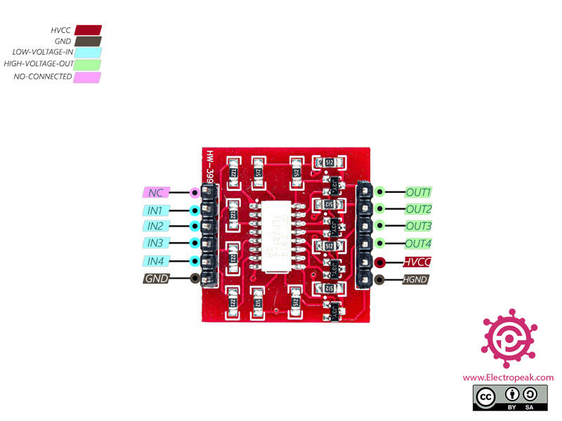
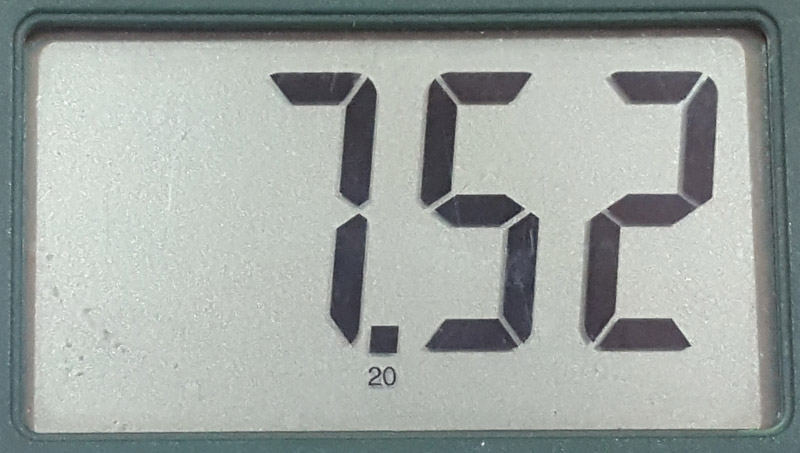
    Did the author really build the circuit? The diagram shows the input connected to the NC. Also the outputs of this board are sinking. ie. The transistor connects the load to ground. Don’t know how you would get 7.52 volts at the output pin????

    December 15, 2021 at 1:21 am
    • Mehran Maleki Reply

      Hi.
      All circuits are built and tested before posting the article. Unfortunately, there has been a slight mistake in photoshopping the circuit diagram. Now it’s modified, and the article has been updated. Thank you for your attention.

      December 18, 2021 at 10:39 am

Leave a Reply

Your email address will not be published. Required fields are marked *