
Overview
LEDs can uniquely control the amount of three primary colors (red, green, and blue) to create a desired color. Thanks to this feature, they are now an attractive and practical component in Electronics and Lighting industry. An RGB LED has one common pin as well as three pins for red, green, and blue colors. We can combine these primary colors to create countless colors by controlling these pins with a PWM pulse signal. (The number of colors depends on the resolution of the generated PWM signal).
These components are controlled by microcontrollers and PWM drivers. But, since each microcontroller has a limited number of pins and output current, various modules have been developed to increase PWM channels for controlling RGB LEDs.
TLC5947, which has 24 PWM output channels, is a widely used module. In this tutorial, we’ll introduce and set up this module.
An Introduction to TLC5947 Modules
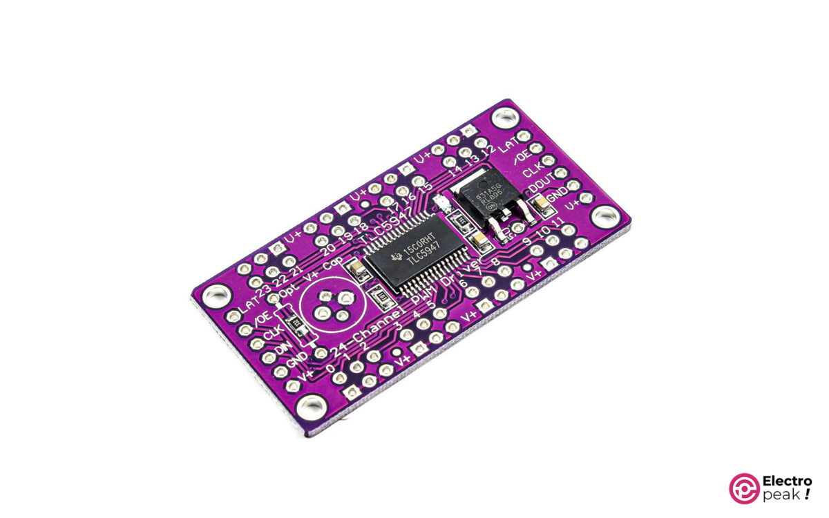
The TLC5947 module is a constant-current LED driver module with 24 output channels. On this module, we can separately control 24 rows of LEDs (or 8 rows of RGB LEDs) with a PWM signal.
The resolution of the PWM signal is 12 bits, meaning 4096 PWM steps are used to handle each output channel.
We communicate with the module through the SPI signal which has a voltage level of 3-5 volts.
Several modules can be connected, all of which are controlled by three data lines. In this way, we can easily have a large number of controllable PWM outputs with only 3 microcontroller pins.
Unlike most electrical components that operate with a constant voltage, LEDs work with a constant current. In this module, the output current of each pin is fixed at 15mA. Of course, in the IC of this module, the current sinks; meaning it flows from the common anode pin to the control pins rather than the other way around.
The output channels of the module are common anode types. These common pins are connected directly to the module input voltage pin.
The input voltage of this module ranges from 5 to 30V. And in order to communicate, the voltage of the data pins should be between 3 to 5V.
Specifications of TLC5947 Module
Input voltage: 5 to 30 volts
- 24 channels; a constant current of 30 mA
- 12-Bit (4096 Steps) PWM
- CMOS Logic Level I/O
- Data transfer frequency: 30 MHz (board used alone)
- Data transfer frequency: 15 MHz (cascaded devices)
- 4MHz internal oscillator
- Operating temperature: -40 to 85 °C
- Dimensions: 25.90 x 51.40 mm
For more information, check out the module datasheet. Below are the datasheets for the PWM control module and the TLC5947 IC.
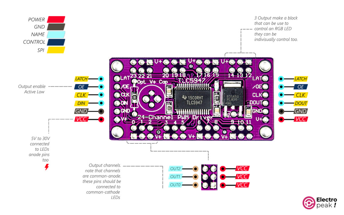
Pinout of TLC5947 Module
- VCC: 5 to 30 volts (module power supply and outputs)
- GND: ground
- DIN: data in
- CLK: clock pin
- LATCH: LATCH pin
- OE: Output Enable, Active LOW (if you pull this pin HIGH, all outputs will become inactive)
Required Materials
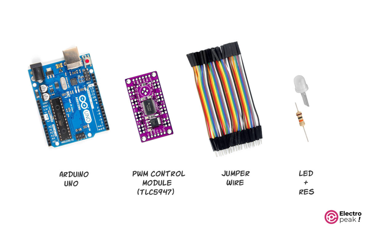
Hardware Components
Software
Interfacing TLC5947 PWM Module with Arduino
Step 1: Wiring
Connect the circuit as shown below.
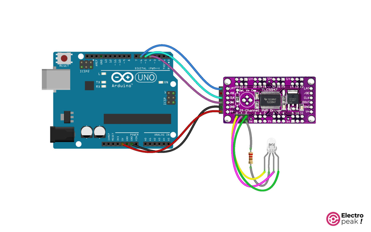
As you can see, a 220Ω resistor is connected, on one side, to the common pin of the common-anode RGB LED, and to the V+ pin, on the other side.
Step 2: Library Installation
Required library: Adafruit_TLC5947
If you need more help installing the library, click on this link.
Step 3: Code
Copy and run the following code in Arduino.
/***************************************************
 * TLC5947 TEST base on adafruit library example
 * electropeak
 * ALi Akbar Hosseini
 These drivers uses SPI to communicate, 3 pins are required to
 interface: Data, Clock and Latch. The boards are chainable

 Fixed typo in all occurences of NUM_TLC5947 (was 5974)
 ****************************************************/

#include "Adafruit_TLC5947.h"
// How many boards do you have chained?
#define NUM_TLC5947 1

#define data 4 //DIN changeable
#define clock 5 //CLK changeable
#define latch 6 //LAT changeable
#define oe -1 // set to -1 to not use the enable pin (its optional)

Adafruit_TLC5947 tlc = Adafruit_TLC5947(NUM_TLC5947, clock, data, latch);

void setup() {
 Serial.begin(9600);
 Serial.println("TLC5947 test");
 tlc.begin();
 if (oe >= 0) {
 pinMode(oe, OUTPUT);
 digitalWrite(oe, LOW);
 }
}

void loop() {
 tlc.setLED(0,4059,0,0);//out number 0 fully on
 tlc.write();
 delay(200);
 tlc.setLED(0,0,4095,0);//out number 1 fully on
 tlc.write();
 delay(200);
 tlc.setLED(0,0,0,4059);//out number 2 fully on
 tlc.write();
 delay(200);
 //use premade functions
 colorWipe(4095, 0, 0, 100); // "Red" (depending on your LED wiring)
 delay(200);
 colorWipe(0, 4095, 0, 100); // "Green" (depending on your LED wiring)
 delay(200);
 colorWipe(0, 0, 4095, 100); // "Blue" (depending on your LED wiring)
 delay(200);
 rainbowCycle(10);

}


// Fill the dots one after the other with a color
void colorWipe(uint16_t r, uint16_t g, uint16_t b, uint8_t wait) {
 for(uint16_t i=0; i<8*NUM_TLC5947; i++) {
 tlc.setLED(i, r, g, b);
 tlc.write();
 delay(wait);
 }
}

// Slightly different, this makes the rainbow equally distributed throughout
void rainbowCycle(uint8_t wait) {
 uint32_t i, j;

 for(j=0; j<4096; j++) { // 1 cycle of all colors on wheel
 for(i=0; i< 8*NUM_TLC5947; i++) {
 Wheel(i, ((i * 4096 / (8*NUM_TLC5947)) + j) & 4095);
 }
 tlc.write();
 delay(wait);
 }
}

// Input a value 0 to 4095 to get a color value.
// The colours are a transition r - g - b - back to r.
void Wheel(uint8_t ledn, uint16_t WheelPos) {
 if(WheelPos < 1365) {
 tlc.setLED(ledn, 3*WheelPos, 4095 - 3*WheelPos, 0);
 } else if(WheelPos < 2731) {
 WheelPos -= 1365;
 tlc.setLED(ledn, 4095 - 3*WheelPos, 0, 3*WheelPos);
 } else {
 WheelPos -= 2731;
 tlc.setLED(ledn, 0, 3*WheelPos, 4095 - 3*WheelPos);
 }
}
A brief explanation of the code above:
We have fully turned on the output channel #0 with the following commands.
  tlc.setLED(0,4059,0,0);//out number 0 fully on
  tlc.write();
The first argument specifies the output block number. Every three output pins form a block together. The next three numbers, each corresponding to one of these three outputs, indicate the degree to which (on a scale of 1 to 4059) they should be turned on.
In the command above, we turned on the first three outputs of the first block, one after the other, with a delay of 200 ms.
In the next part, all of the output pins are tested using the functions defined at the end of the code.
Cascade Setup of Several TLC5947 PWM Control Modules
The “cascade” feature in these modules allows us to connect a large number of modules, so we will have more output pins. We can also control all of these outputs with only three pins. And since we have more outputs, providing proper power for them is one of the most important things we should consider.
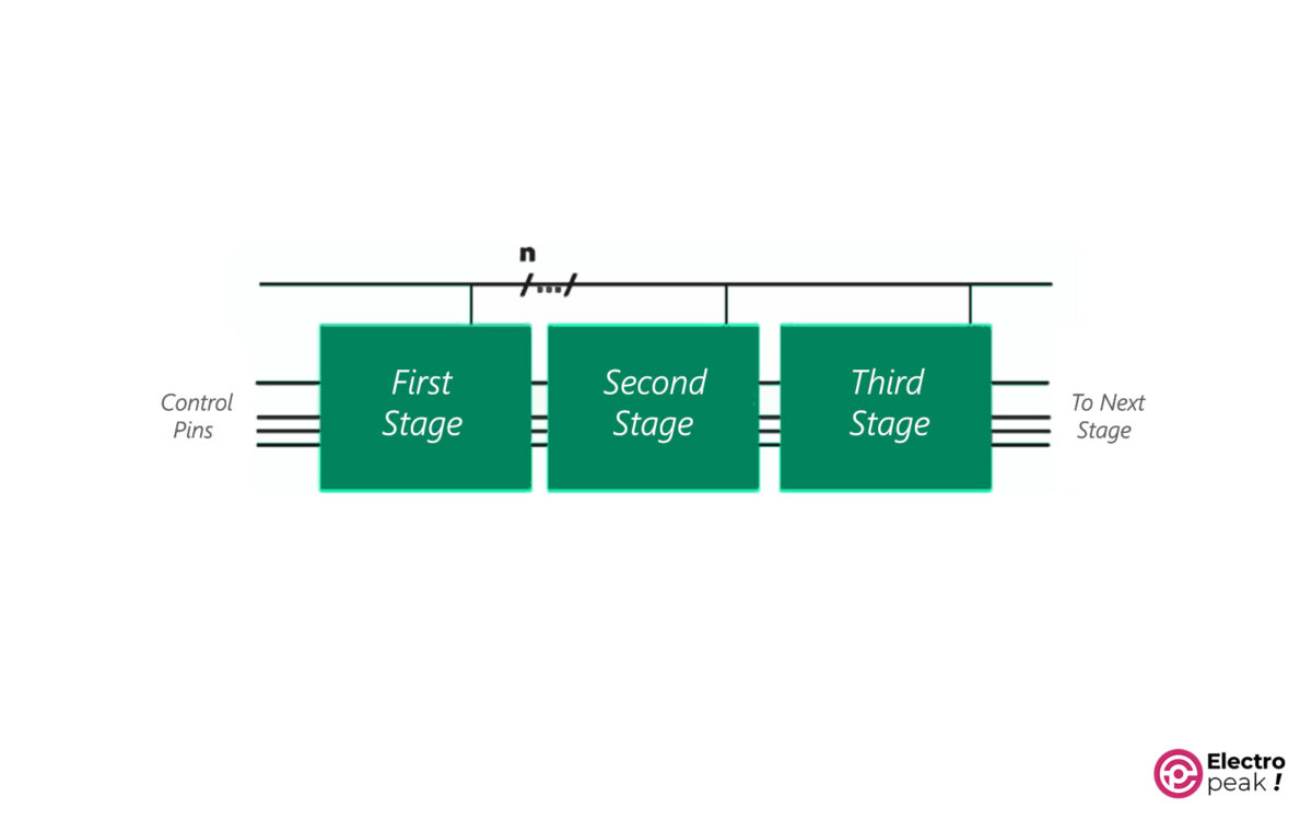
CASCADE Feature in Modules
When cascading modules or ICs, a number of them can be connected in series, stage by stage. We can, therefore, control the remaining stages with the control lines of the first block (stage). In a CASCADE structure, data and commands are transferred from one stage to another, and the set acts as an expanded unit of building blocks.
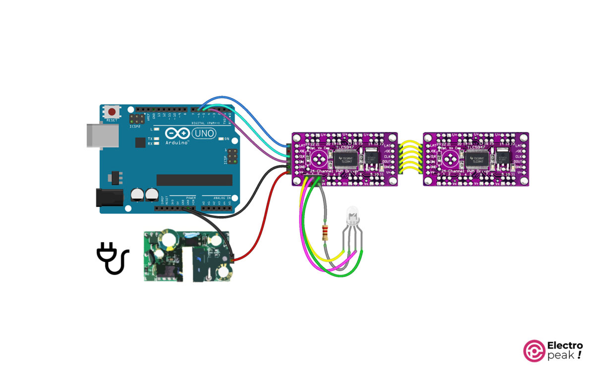
To cascade the PWM control module, you can simply connect these modules as shown above. Use a separate power supply with suitable current and voltage to feed the modules. For accurate calculation of power supply parameters, check out the IC datasheet.
Hardware Components
* We will use a 5V power supply.
Wiring
Code
To work with two modules, just change one line in the above code.
#define NUM_TLC5947 2
With this line, we specify the number of modules connected and use this number in the functions to test all the outputs.
