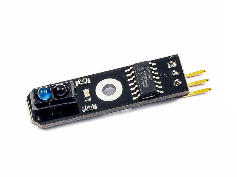
This sensor which is mostly used for line tracking, works like motion detection sensors. It is based on TCRT5000 IC. The TCRT5000 is a sensor that emits infrared light continuously. If the transmitted wave is not reflected or is reflected very poorly, the output will be LOW. If you put an object in front of this sensor, the output becomes HIGH.
Note
Black color absorbs the transmittedIR radiation and reflects it very poorly. So the output will be LOW if there is a black object in front of the sensor. But if other colors are placed in front of the sensor, the output becomes HIGH.
*/
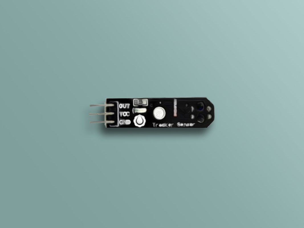
int GND = 5;
int VCC = 6;
int OUT = 7;
void setup() {
// initialize serial communication at 9600 bits per second:
pinMode(GND, OUTPUT);
pinMode(VCC, OUTPUT);
pinMode(OUT, INPUT);
digitalWrite(GND, LOW);
digitalWrite(VCC, HIGH);
Serial.begin(9600);
}
void loop() {
int sensorValue = digitalRead(OUT);
if (sensorValue == 0){
Serial.println("black color");
}
if (sensorValue == 1){
Serial.println("other colors");
}
delay(500);
}
In this program, we set pin 5 and 6 to Low and High so we can use them as the ground and VCC, respectively. And we set pin 7 to digital input and check the sensor output constantly. If this pin is HIGH, it means that there is no black object in front of the sensor, but if we place a black object or nothing in front of it, the output becomes LOW.
We place different colors, including black, in front of the sensor. Only when the color is not black, the output will be HIGH and the phrase “other colors” is displayed: