Contents

Interfacing TB6612FNG Dual Motor Driver with Arduino

TB6612FNG Dual Motor Driver Features

Today, controlling the speed and direction of DC motors is very important due to their many applications. The most common method of controlling DC motors is the H-Bridge. This method allows you to control both the speed and the direction of the engine. The TB6612FNG dual module uses the same method to control two motors.

One of the control pins of this module is PWM. This pin is connected to the gate of the transistor. The longer the duty cycle, the higher the voltage and, as a result, the faster the motor rotates.

The motor working voltage is in the range of 2.7 to 13.5V and the maximum output current is up to 1.2 A per channel.

Note
The efficiency of this module is 91 to 95%.

You can download the datasheet of this module here.

TB6612FNG Dual Motor Driver Module Pinout

This sensor has 16 pins:

  • VM: Motor voltage
  • VCC: Module power supply
  • GND: Ground – In this module we have three ground pins that are connected to each other.
  • A1: Motor A connection ‘+’
  • A2: Motor A connection ‘-‘
  • B1: Motor A connection ‘+’
  • B2: Motor A connection ‘-’
  • PWMA: PWM pin for Motor A for speed control
  • PWMB: PWM pin for Motor B for speed control
  • AIN1: Control signal for motor A
  • AIN2: Control signal for motor A
  • BIN1: Control signal for motor B
  • BIN2: Control signal for motor B
  • STBY: This PIN must be HIGH to activate Standby

You can see the pinout of this module in the image below.

Note that with different modes of control signals, motor performance varies. The table below shows the different modes of operation.

Required Materials

Hardware Components

Arduino UNO R3 × 1
TB6612FNG Dual Motor Driver Module × 1
6V DC Motor × 2
10K Potentiometer × 1
9V Battery × 1
9V Battery Clips with Bare Leads × 1
Male to Female jumper wire × 1
Male to Male jumper wire × 1
400 Tie point Breadboard × 1

Software Apps

Arduino IDE

Interfacing TB6612FNG Dual Motor Driver Module with Arduino

Step 1: Circuit

The following circuit shows how you should connect Arduino to TB6612FNG module. Connect wires accordingly.

Note
Connect the STBY pin to the VCC.

Step 2: Code

Upload the following code to your Arduino.

    /*
  TB6612FNG-Dual-Driver
  made on 28 oct 2020
  by Amir Mohammad Shojaee @ Electropeak
  
Home
*/ #define PWM1 3 #define AIN1 4 #define AIN2 5 #define PWM2 6 #define BIN1 7 #define BIN2 8 int pot; int out; void setup() { Serial.begin(9600); pinMode(PWM1,OUTPUT); pinMode(AIN1,OUTPUT); pinMode(AIN2,OUTPUT); pinMode(PWM2,OUTPUT); pinMode(BIN1,OUTPUT); pinMode(BIN2,OUTPUT); } void loop() { digitalWrite(AIN1,HIGH); //Motor A Rotate Clockwise digitalWrite(AIN2,LOW); digitalWrite(BIN1,HIGH); //Motor B Rotate Clockwise digitalWrite(BIN2,LOW); pot=analogRead(A0); out=map(pot,0,1023,0,255); analogWrite(PWM1,out); //Speed control of Motor A analogWrite(PWM2,out); //Speed control of Motor B }

This code enables you to control 2 DC motors simultaneously. By turning the potentiometer, the speed of the motors increases in a clockwise direction.

Warning

Be careful not to fully turn the pententiometer because your motor is a 6 volts motor DC and the input voltage is 9 volts and the motor may be damaged. Of course, you can use a lower voltage battery or a higher voltage motor.

Liked What You See?​
Get Updates And Learn From The Best​

Comments (8)

  • Malcolm Palmer Reply

    Does the TB6612FNG work with ESP 32 or Lolin 32?
    If so, what is the hookup pins for these modules.

    July 11, 2021 at 3:21 pm
    • Mehran Maleki Reply

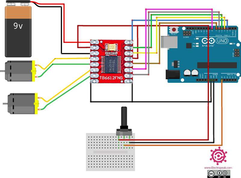
      Yes, you can use TB6612FNG with all types of microcontrollers including ESP32 and Lilin32 which is also an ESP32-based board. And this is how you can do that:
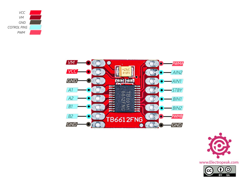
      As you can see in the circuit, 6 pins of the Arduino Board are connected to the TB6612FNG module. You can also see that 6 pins have been defined at the beginning of the code. If you want to use an ESP32 board instead of the Arduino Board we have used, all you need to do is to choose any 6 GPIO pins of your ESP32 and change those 6 lines of the code accordingly. And also do the wiring based on the new definitions. Hope you can make work! Good luck.

      July 12, 2021 at 7:15 am
  • Roy Reply

    Can you give a schematic of the TB6612FNG with a Arduino Pro Micro?? I want to use this combo to run 2 small motors on my Logitech G29 Pedals, which uses a Uno initially.

    May 11, 2022 at 11:17 pm
    • Mehran Maleki Reply

      There is no special difference between using an Arduino Uno and an Arduino Pro Micro. You can connect the pins of the TB6612FNG module to any of the digital pins of Arduino Pro Micro. Also pay attention that pins PWM1 and PWM2 of the TB6612FNG must be connected to pwm pins of your Arduino Pro Micro. You also need an analog pin for controlling the potentiometer. One last thing, make sure you change the lines 9-14 of the code according to the new wiring.

      May 14, 2022 at 7:21 pm
  • saeed Reply

    what if i want to use separate power for 5v and 12v should I connect their gnd all together? which one should go to motor driver?? it has both 5v 12v unlike duino

    April 15, 2023 at 4:17 am
    • Mohammad Damirchi Reply

      You should connect all GNDs together, the 12V to the VM of TB6612, and the 5V to the VCC of TB6612 and Arduino VIN

      April 15, 2023 at 8:50 am
      • Michal Katalov Reply

        crazy shit im not learnin all that xDDD

        April 24, 2024 at 9:32 am
        • Mohammad Damirchi Reply

          Hi Michal,
          How may I be of assistance to you?

          April 27, 2024 at 5:47 am

Leave a Reply

Your email address will not be published. Required fields are marked *